61
Part 1 Installation Chapter 6 Safety Circuit
Part 1 Installation
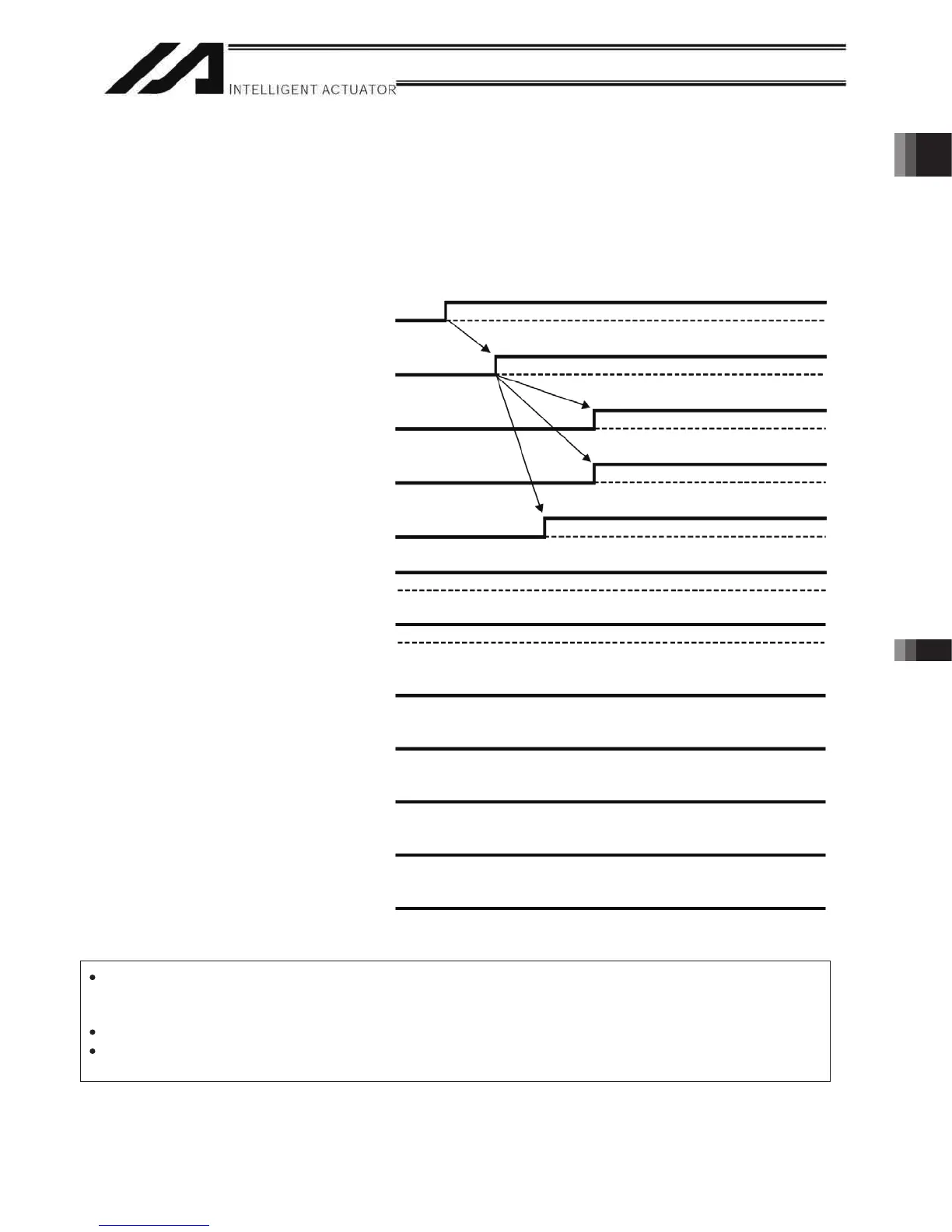
4. Safety Circuit Timing Charts for Q/QCT type SEL Controller
Safety circuit timing charts for Q/QCT type SEL controller are shown below.
The timings covered by the timing charts are as follows: [1], “Power on,” [2], “Emergency stop,” [3], “Power on
during emergency stop,” [4], “Enable input,” [5], “System-shutdown level error,” [6], “Cold-start level error,” [7],
“Operation-cancellation level error,” [8], “Power on (combined with cutoff reset input), [9], “Emergency stop
(combined with cutoff reset input)”
[1] Power on
I/O parameter No. 24, bits 0 to 3 = 0: The RDYOUT output (system I/O) is SYSRDY (PIO trigger
program can be run) and the hardware is normal (emergency stop
is not actuated and hardware error is not detected).
I/O parameter No. 44 = 0: The drive-source cutoff reset input is not used.
I/O parameter No. 47 = 3: Output function 301 = READY output (PIO program can be run
and error of cold-start level or higher is not present).
200-VAC control power supply
Successful startup of CPU
I/O output signal: Port No. 301
Ready output
Rdy (system I/O)
SDN (system I/O)
EMG1/EMG2 (system I/O)
ENB1/ENB2 (system I/O)
Occurrence of secret level error
Occurrence of message level error
Occurrence of operation-cancellation level error
Occurrence of cold-start level error
Occurrence of system-shutdown level error

 Loading...


