60
Part 1 InstallationChapter 6 Safety Circuit
Part 1 Installation
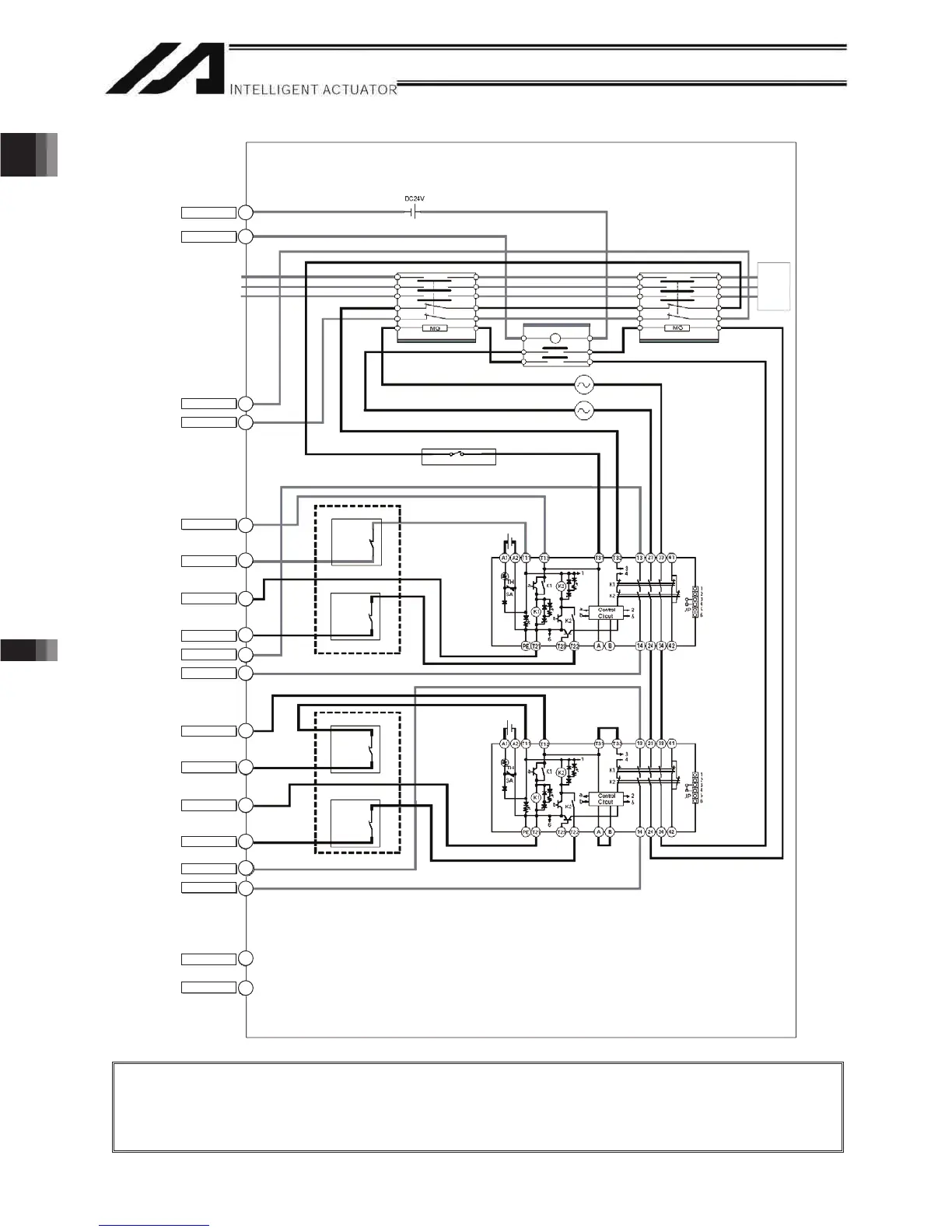
External Emergency-Stop Circuit
Contactor (NEO SC)
Relay
Contactor (NEO SC)
200-VAC,
three-
phase
Reset switch
External emergency-stop switch
External
EMG switch
Safety relay unit
(G9SA-301 by Omron)
Safety gate switch
External
SGATE
contact 1
External
SGATE
contact 2
14
15
(Note)
(Note)
8
4
7
3
5
6
18
9
2
1
17
16
12
13
11
10
SDN Out–
SDN Out+
DET +24V
DET IN
EMG line+
EMG line–
EMG2 line+
EMG line–
EMGin +24V
EMGin IN
ENB1 line+
ENB1 line–
ENB2 line+
ENB2 line–
ENBin +24V
ENBin IN
RDY Out–
RDY Out+
Note: It is recommended to connect ENB1 line+ to 14 and ENB1 line- to 15 so the unit would not
get burned even if a standard PC cable (black) is connected accidently to Q/QCT Type.
(There should be no problem even if 14 and 15 are swapped around if the appropriate PC cable
(gray) is applied.)
contact 1
External
EMG switch
contact 2

 Loading...


