71
Part 1 Installation Chapter 7 System Setup
Part 1 Installation
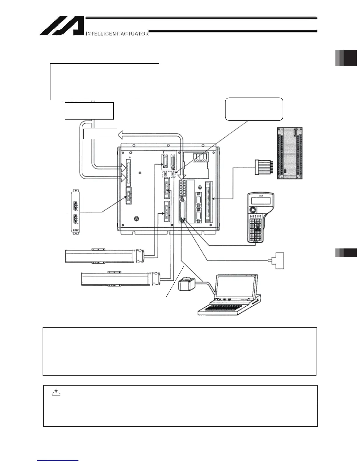
1.2 Connection Diagram for Q/QCT Type (Global Specification)
Note 1: With the absolute specification, set the absolute-data backup battery enable/disable switch
to the bottom position for all axes before connecting the encoder/axis-sensor cables. (After
the cables have been connected and power turned on, set the switch back to the top
position.)
Note 2: Connect the supplied dummy plug to the teaching connector if neither a teaching pendant
nor PC cable (PC software) is connected to this connector.
Auxiliary power
device circuit
Absolute-data backup
battery enable/disable
switch
Safety circuit
Axis 1
Regenerative
unit
Host system
(PLC)
Teaching
pendan
(optional)
PC
Axis 2
Dummy plug
(AUTO mode)
Single-phase specification
CP: Single-phase, 200 to 230-VAC power source
MP: Three-phase, 200 to 230-VAC power source
Three-phase specification
CP: Single-phase, 200 to 230-VAC power source
MP: Three-phase, 200 to 230-VAC power source
PC connection cable
CB-ST-A1MW050
PC software IA-101-XA-MW
ً
Warning : The internal components of the controller may burn if the following cable is used to connect
XSEL-Q/QCT to a computer.
Even though the PC software can be used, make sure to use the cable CB-ST-A1MW050
(gray).
• Standard PC cable CB-ST-E1MW050 (black) enclosed in PC Software IA-101-X-MW
* CB-ST-E1MW050
cannot be used.

 Loading...


