72
Part 1 InstallationChapter 7 System Setup
Part 1 Installation
1.3 Startup procedure
Note: When installing multiple axes to the controller, be sure to connect the actuator cables to the
right connectors. Check the type of the actuator connected to each connector. If the cables
and connectors are not connected properly, motor/board damage or malfunction may result.
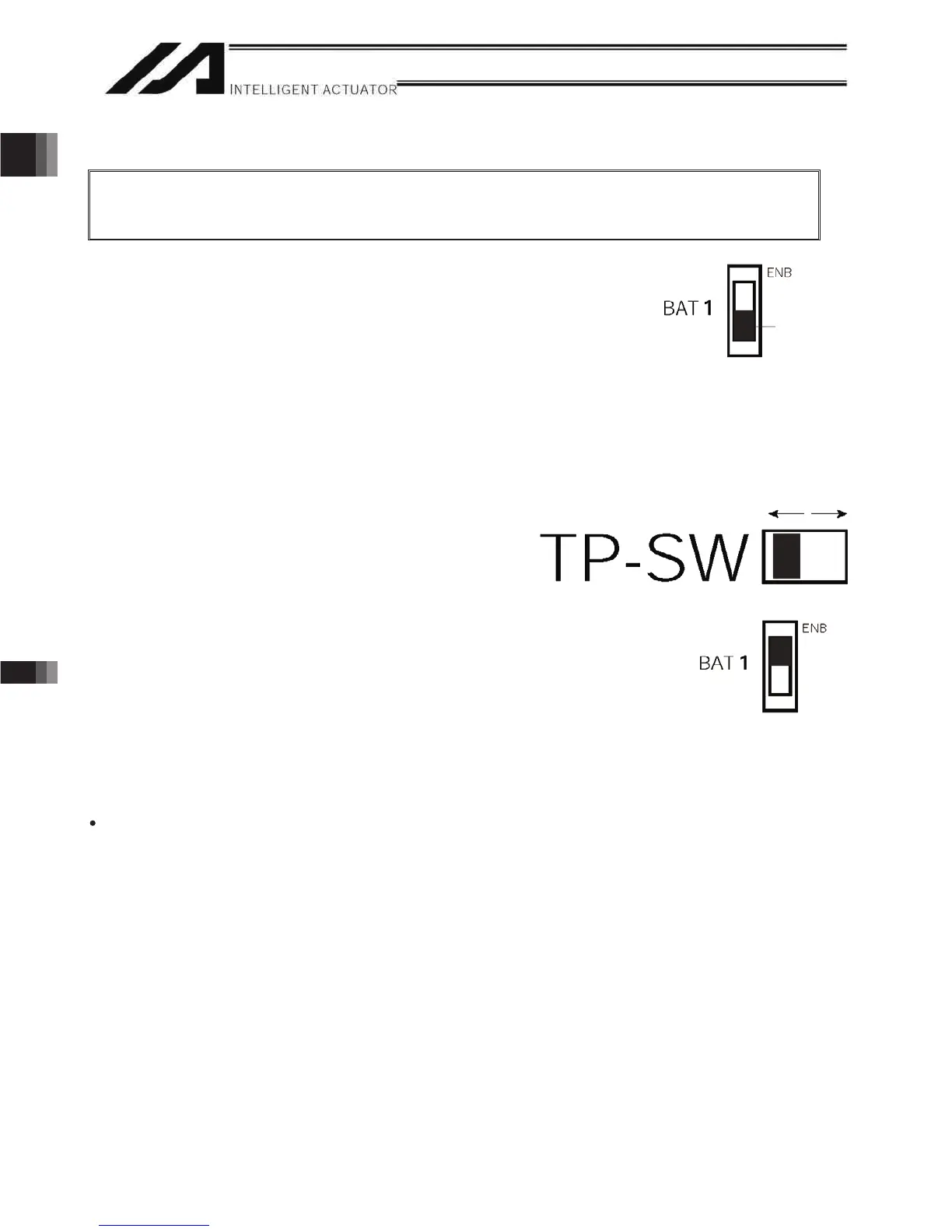
1. If your controller is of the absolute specification, set the absolute-data backup
battery enable/disable switch to the bottom position for all axes.
2. Connect to the controller the motor cable, encoder cable and LS cables
(optional) from the actuator. Before turning on the power, be sure to confirm
that each connector on the controller is connected to the correct actuator.
3. Connect the teaching pendant cable to the teaching connector. Once the teaching pendant has been
connected, set the mode switch to MANU (top position).
(If the mode switch is set to AUTO, the teaching pendant and RS-232 communication function will not
operate after the power is turned on.) (P/PCT type only)
4. Set the teaching-pendant type switch.
(Note 1) Q/QCT type controllers have no TP-SW.
(Note 2) Q/QCT type controllers cannot be used with IAI’s standard teaching pendants or standard PC cables.
Left: SEL-T, SEL-TD, SEL-TG teaching pendant
IA-T-XA teaching pendant
Right: PC cable |
IA-T-X, IA-T-XD teaching pendant
5. Turn on the controller power.
6. If your controller is of the absolute specification, set the
absolute-data backup battery enable/disable switch to the
top position (ENB) for all axes.
7. The panel window will show the code “rdy,” indicating that
the controller is ready. If “ErG” is shown on the panel
window, it means an emergency stop signal has been input.
Reset the emergency stop.
If your controller is of the absolute specification, “E914” or
“ECA2” will be shown. Refer to Chapter 8, “How to Perform An Absolute Encoder Reset.”
The controller is now ready to operate.
The RDY terminals (10, 11) in the system I/O connector are relay contact terminals that are shorted when the
controller is ready.
Set to the bottom
position to disable.
Switch

 Loading...


