EasyManuals Logo
Home>IBM>Server>P 615 series

IBM P 615 series User Manual

IBM P 615 series
491 pages
To Next Page IconTo Next Page
To Previous Page IconTo Previous Page
Page #429 background imageLoading...
Page #429 background image
4
2
1
3
5
6
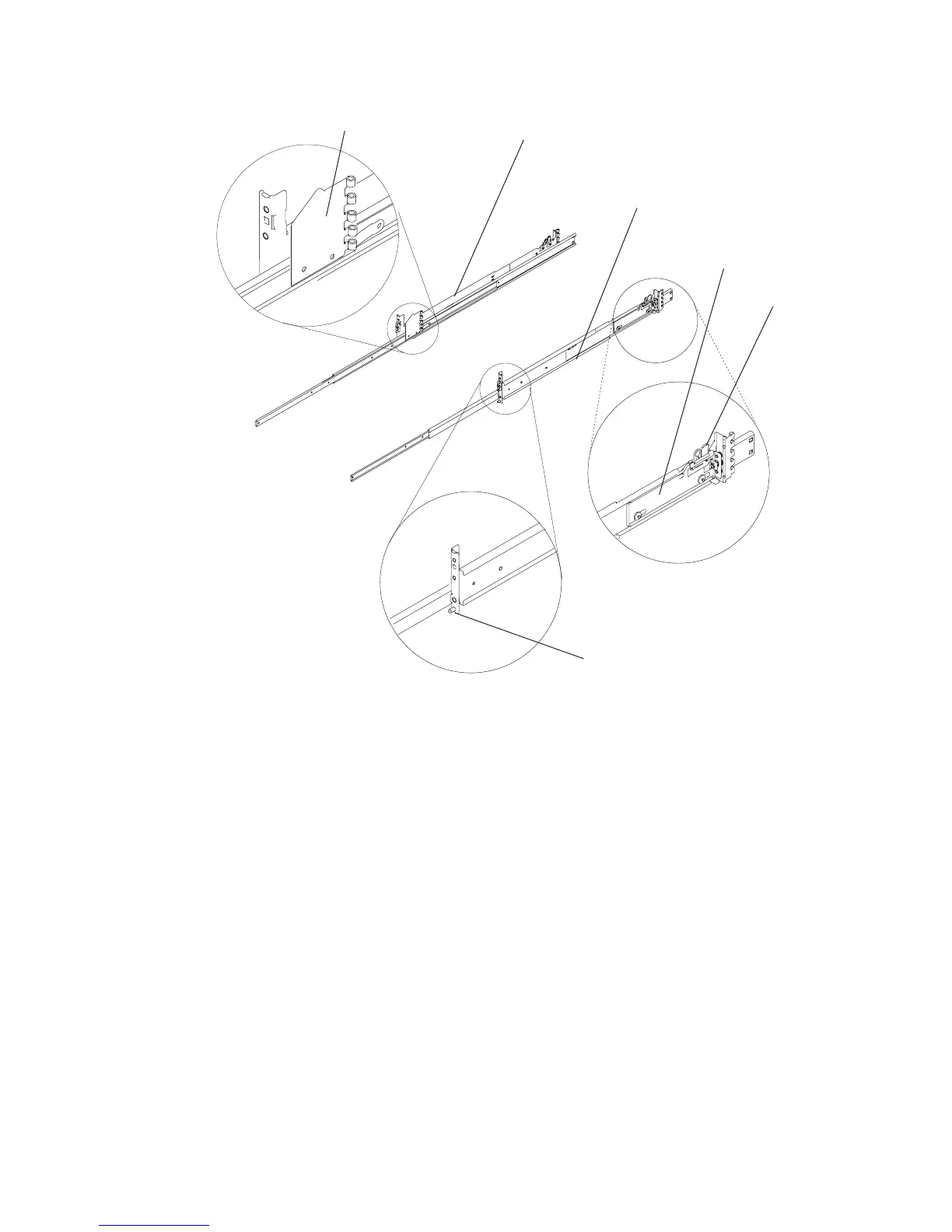
1
Left
rail
assembly
4
Rail-mounting
latch
release
tab,
rear
2
Right
rail
assembly
5
Rail-mounting
hardware,
front
right
3
Rail-mounting
latch
assembly,
rear
6
Cable-management
arm
flange
2.
Remove
the
front
and
rear
rack
doors
if
necessary.
For
7014
Model
T00
and
T42
racks,
refer
to
7014
Model
T00
and
T42
Rack
Installation
and
Service
Guide,
order
number
SA38-0577,
for
information
about
removing
the
rack
doors.
3.
Locate
the
rack-mounting
template.
If
you
do
not
have
a
rack-mounting
template,
go
to
substep
6.
4.
Using
the
rack-mounting
template,
determine
where
in
the
rack
to
place
the
system.
Make
note
of
the
Electronics
Industries
Association
(EIA)
location
number.
Note:
The
rack-mounting
template
has
printed
illustrations
located
on
the
front
of
the
template.
Each
illustration
is
designed
to
aid
in
identifying
the
EIA
location
holes
used
when
planning
to
populate
your
rack.
Do
not
use
the
rack-mounting
template
without
reading
and
understanding
the
following
substeps.
Each
step
must
be
completed
in
its
entirety.
5.
Note
the
following
when
using
the
rack-mounting
template:
v
Each
black
or
white
unit
on
the
template
is
equal
to
1
EIA
unit.
v
Each
EIA
unit
consists
of
three
holes.
v
The
EIA
units
illustrated
on
the
template
must
be
aligned
with
the
EIA
units
located
on
the
rack.
Appendix
D.
Setting
Up
the
System
409

Table of Contents

Questions and Answers:

Question and Answer IconNeed help?

Do you have a question about the IBM P 615 series and is the answer not in the manual?

IBM P 615 series Specifications

General IconGeneral
BrandIBM
ModelP 615 series
CategoryServer
LanguageEnglish

Related product manuals