Chapter 1. Reference Information
This chapter provides an overview of the models S80 and S85. This includes a logical
description and a physical overview of the system. Additional details pertaining to the
models S80 and S85 are also provided. These include:
v Memory overview and ordering rules
v General description of the operator panel
v Cabling rules
v System location rules and descriptions
v Powering on and off the system
v Power flow
v Data flow
Models S80 and S85 Overview
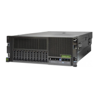
The models S80 and S85 systems are exclusively multi-processor, multi-bus systems
packaged in two different rack types. The processors and memory are packaged in the
system rack and the DASD and I/O devices are in I/O drawers. The basic system
consists of one system rack and one I/O drawer in a separate rack. The system is
expandable to one system rack and four I/O drawers in up to four I/O racks. Connection
between the system rack and subsequent I/O drawers is made through a number of
cables, which include SPCN (system power control network), RIO (remote input output),
JTAG, and operator panel cables.
The system rack is powered independently from the I/O drawer. The system rack
supports a minimum of one processor card to a maximum of four. Each processor card
has six processors, each having its own L2 cache. The system memory is controlled
through a multi-port controller complex and supports up to 16 memory slots. The total
memory available to the system user is dependent on the memory feature card installed
and the number of memory cards. All system memory resides in the system rack.
Additional major functional units in the system rack include the operator panel and
control circuitry, the SPCN controller, interrupt, and system bus control logic. Power is
brought into the system rack through an ac power cord (200 - 240 V ac), distributed to
six bulk supplies and then fed through regulators for both system resources and logic
and memory.
The I/O rack holds the I/O drawer, which provides for up to 14 PCI adapters per drawer.
Four distinct peripheral component interface (PCI) buses are present in each I/O
drawer. The primary I/O drawer (drawer 0) has PCI slots 6, 7, 8, and 13 reserved for
the system media, Service Processor and DASD bays resident in the I/O drawer. These
slots are available in subsequent I/O drawers 1 through 3 for any supported PCI
adapter to use. The PCI bus speed is 33Mhz with both 32- and 64- bit adapters
supported on a slot basis. Slots 1, 5, 9, 10 and 14 support either 32- or 64- bit PCI
adapters. The remaining slots are 32 bit only. “Models S80 and S85 Data Flow” on
page 2 illustrates the system data flow.
The I/O drawer provides space for up to three media devices (tape, CD-ROM, and
diskette drive) and two DASD bays, each holding up to six disk drives.
© Copyright IBM Corp. 1999, 2000 1

 Loading...


