RIO Cabling
The following rules apply to RIO cable connections:
v I/O drawers 0 and 1 are connected using the first RIO loop, which uses RIO ports 0
and 1 on the system rack.
v I/O drawers 2 and 3 are connected using the second RIO loop, which uses RIO ports
2 and 3 on the system rack.
v The primary I/O drawer must be installed and connected to RIO port 0 of the system
rack. The connection must be made from RI0 port 0 of the system rack to RIO port 0
of the primary I/O drawer. This connection is required to make the primary drawer the
first drawer in the loop, which allows the firmware to initialize the system.
v If the loop connection between RIO 2 and RIO 3 is broken, the system is not able to
differentiate between I/O drawer 2 and I/O drawer 3. The system still conillustrations
RIO 0 and RIO 1 ports, but does not conillustration RIO 2 or RIO 3 ports.
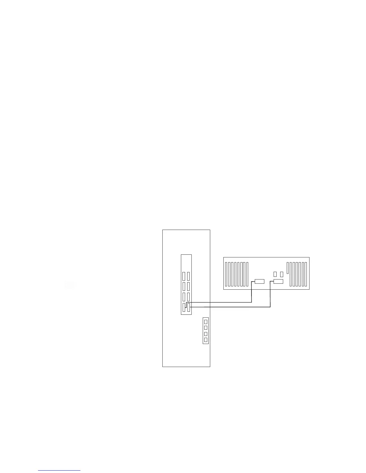
The following illustrations provide cabling examples for all valid cabling configurations.
Match your configuration to the correct illustration and connect your RIO cables as
shown.
System Rack Attached to One I/O Drawer
21
SPCN
RIO 1RIO 0
Drawer 0, Primary
RIO 1
RIO 0
RIO 2
RIO 3
J14
J11
SPCN 0, J15
SPCN 1, J16
Chapter 1. Reference Information 33