6. Note the location of any cables connected to the service processor card, and then
disconnect them.
7. If SCSI cables are routed over the service processor card, disconnect them from the
SCSI adapter.
8. Remove the screw that secures the service processor card bracket to the system
chassis.
9. Remove the service processor card by pulling it straight up.
Replacement
Replace in reverse order.
Note: A service processor firmware update is required if other than the original version
is on the system. Refer to “Appendix F. Firmware Update Procedures” on
page 615 for instructions on obtaining, downloading, and installing the latest level
firmware. If a backup set of diskettes exists from a prior update, these can be
used.
Attention: When the service processor card is replaced, the vital product data (VPD)
must be reprogrammed. perform the procedure in “Appendix E. System Vital Product
Data” on page 613 before you return the system to normal operations.
1. Use the System Management Interface Tool (SMIT) to reset the system date and
time
2. Advise the customer to reset his passwords. Passwords can be set using the
service processor menus. See “Chapter 7. Service Processor Menus” on page 447
for more information. The service processor menus also are used to reset the
service processor call-in functions after a service processor card replacement. See
“Chapter 7. Service Processor Menus” on page 447 and “Service Processor Call-In
Security” on page 471 for more information.
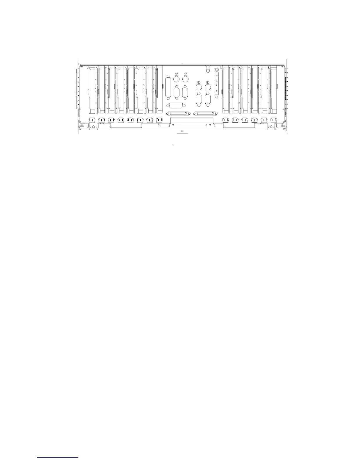
Attention: To prevent damage to cards in the drawer, refer to the figure on “10
EIA-Unit I/O Drawer Cable Routing” on page 42, and ensure that the cables are routed
correctly.
1
2 3 4 5 6 7 8 9 10 11 12 13 14
Chapter 9. Removal and Replacement Procedures 531
 Loading...


