Replacing a memory module
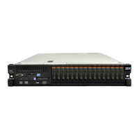
The following illustration shows the location of the DIMM connectors on the
system board.
DIMM 1
DIMM 2
DIMM 3
DIMM 4
DIMM 5
DIMM 6
DIMM 24
DIMM 23
DIMM 22
DIMM 21
DIMM 20
DIMM 19
DIMM 7
DIMM 8
DIMM 9 DIMM 11
DIMM 10
DIMM 18
DIMM 17
DIMM 16DIMM 14
DIMM 15DIMM 12 DIMM 13
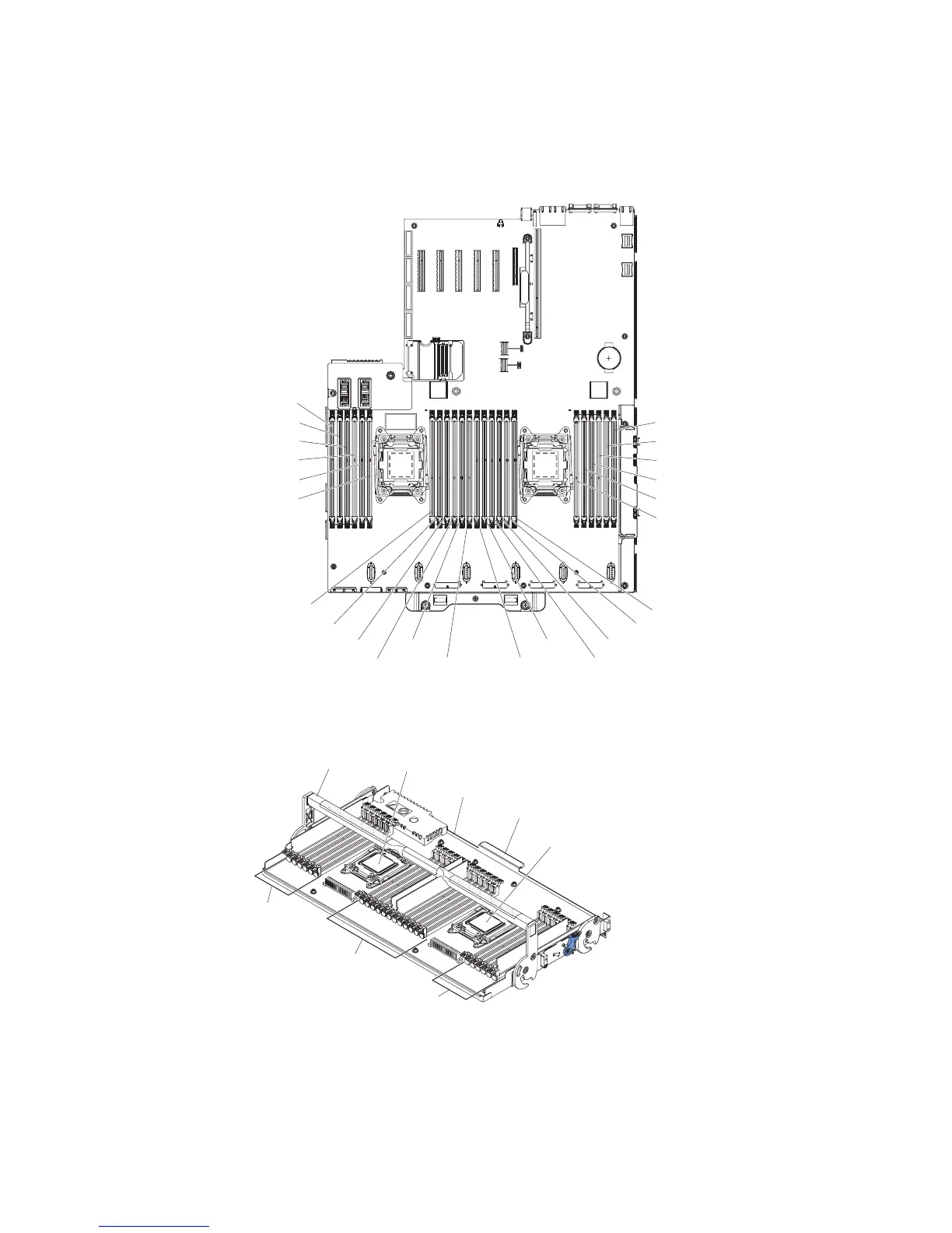
The following illustration shows the location of the DIMMs on the optional
microprocessor and memory expansion tray:
Tray handle
Memory tray
DIMMs
25-30
DIMMs
31-42
DIMMs
43-48
Microprocessor 3
Microprocessor 4
Tray handle
Note:
v See “Installing a memory module” on page 41 for notes and information that
you must consider when you install DIMMs. For DIMM population information,
see “Non-mirroring (independent mode)” on page 44, “Memory mirroring” on
page 44, and “Memory sparing” on page 45.
224 System x3750 M4 Types 8722 and 8733: Installation and Service Guide

 Loading...