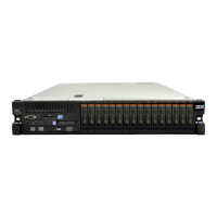
b. Align the holes on the installation tool with the screws on the
microprocessor bracket, then lower the microprocessor installation tool
down over the microprocessor. The installation tool rests flush on the
socket only if it is aligned correctly.
c. Twist the handle on the installation tool clockwise and lift the
microprocessor out of the socket.
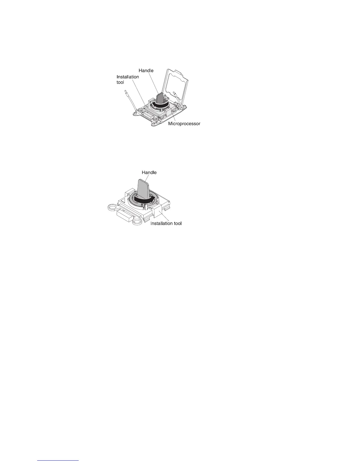
13. Place the microprocessor on a static-protective surface. Remove the
microprocessor from the installation tool by twisting the handle
counterclockwise.
14. If you are instructed to return the microprocessor, follow all packaging
instructions, and use any packaging materials for shipping that are supplied
to you. Do not return the microprocessor installation tool.
Replacing a microprocessor and heat sink
To replace an additional microprocessor and heat sink, complete the following
steps:
Attention: When you handle static-sensitive devices, take precautions to avoid
damage from static electricity. For details about handling these devices, see
“Handling static-sensitive devices” on page 35.
Note:
v This procedure for replacing a microprocessor and heat sink also apply when
replacing a microprocessor and heat sink on the microprocessor and memory
expansion tray.
v See “Installing an additional microprocessor and heat sink” on page 89 for notes
and other information that you must consider when you install a
microprocessor.
v Use the microprocessor installation tool that came with the new microprocessor
kit to remove the microprocessor from the server.
v Be extremely careful when handling the microprocessor, the microprocessor
socket contacts are very fragile.
v The server supports up to four Intel Xeon dual-core or quad-core
microprocessors (two on the base system board and two on the optional
274 System x3750 M4 Types 8722 and 8733: Installation and Service Guide

 Loading...