4. Use a clean area of the cleaning pad to wipe the thermal grease from the
microprocessor; then, dispose of the cleaning pad after all of the thermal grease
is removed.
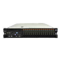
Microprocessor
0.02 mL of thermal
grease
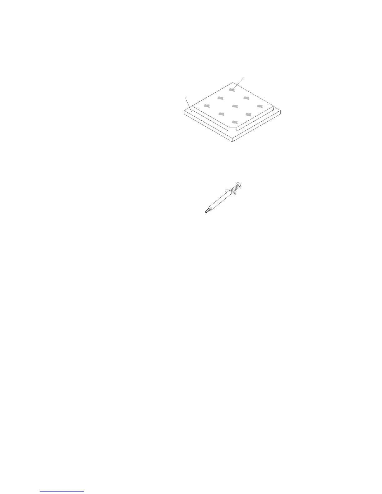
5. Use the thermal-grease syringe to place 9 uniformly spaced dots of 0.02 mL
each on the top of the microprocessor. The outermost dots must be within
approximately 5 mm of the edge of the microprocessor; this is to ensure
uniform distribution of the grease.
Note: If the grease is properly applied, approximately half of the grease will
remain in the syringe.
6. Install the heat sink onto the microprocessor as described in “Replacing a
microprocessor and heat sink” on page 274.
Removing the microprocessor and memory expansion tray
assembly
To remove the microprocessor and memory expansion tray, complete the following
steps:
1. Read the safety information that begins on page “Safety” on page vii and
“Installation guidelines” on page 33.
2. Turn off the server (see “Turning off the server” on page 21) and all attached
peripheral devices. Disconnect all power cords; then, disconnect all external
cables as necessary to replace the device.
3. If the server has been installed in a rack, slide the server out from the rack
enclosure.
4. Remove the top cover (see “Removing the server top cover” on page 206).
5. If power supply 2 is installed, slide it out of the power supply bay slightly.
6. Remove the DIMMs (see “Removing a memory module” on page 223).
7. Remove the microprocessor air baffles (“Removing the microprocessor air
baffle” on page 209).
8. Remove the heat sinks (see “Removing a microprocessor and heat sink” on
page 272 for information on how to remove the heat sinks).
9. Grasp the microprocessor and memory expansion tray front handle by the
blue touch points and rotate it all the way up (this disengages the tray from
the connectors on the system board).
278 System x3750 M4 Types 8722 and 8733: Installation and Service Guide

 Loading...