14
1
PANEL DESCRIPTION
1
!1 SPLIT INDICATOR
Appears during split opeation.
!2 IF FILTER INDICATOR (p. 77)
Shows the selected IF filter number.
!3 PASSBAND WIDTH INDICATOR (p. 77, 79)
Graphically displays the passband width for twin
PBT operation and center frequency for IF shift op-
eration.
!4 MODE INDICATORS
Shows the selected operating mode.
• “-R” appears when CW reverse or RTTY reverse mode
is selected.
!5 PROGRAMMABLE/1 MHz TUNING STEP
INDICATORS
➥
!5a appears when the 1 MHz quick tuning step is
selected.
➥
!5b appears when the programmable tuning step
is selected.
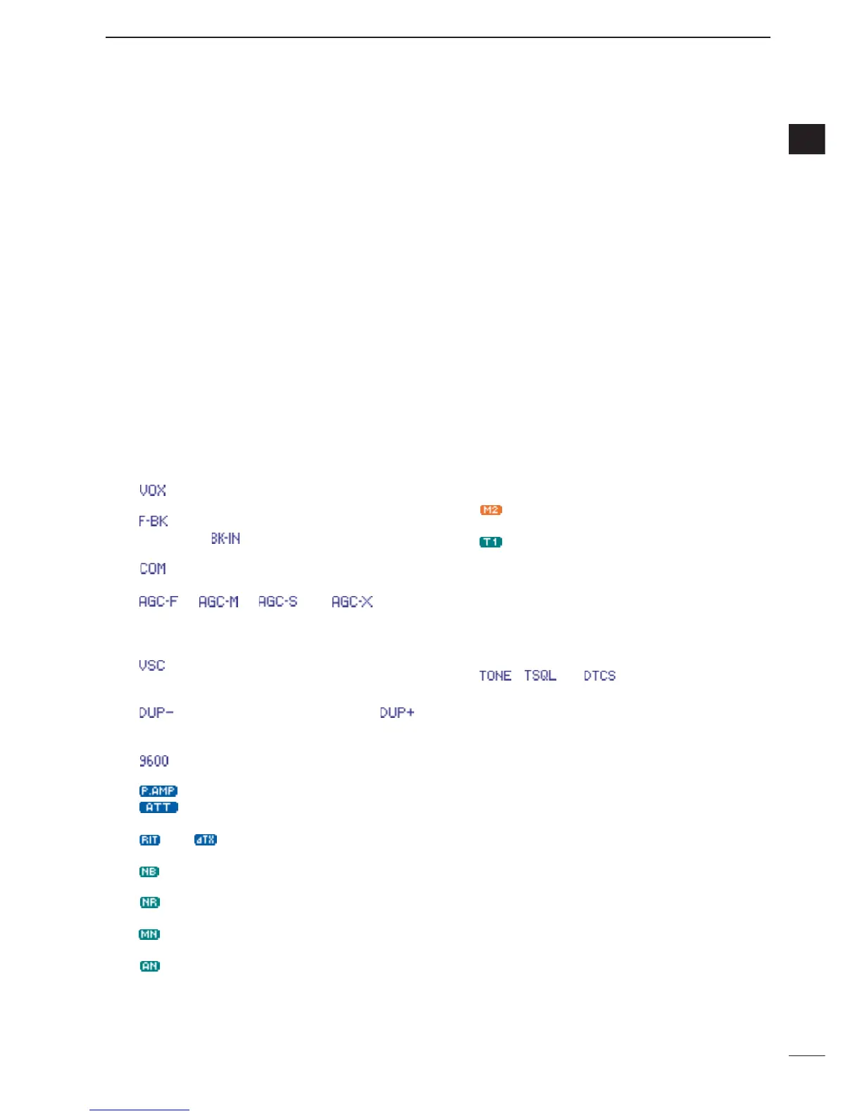
!6 FUNCTION INDICATORS
➥ “ ” appears when the VOX function is acti-
vated.
➥ “ ” appears when full break-in operation is se-
lected and “ ” appears when semi break-in
operation is selected.
➥ “ ” appears when the speech compressor is
activated.
➥ “ ,” “ ,” “ ” or “ ” (OFF)
appears when the fast time constant, middle time
constant, slow time constant or AGC OFF is se-
lected, respectively.
➥ “”appears when the VSC (Voice Squelch
Control) function is activated in phone (SSB, AM,
FM, WFM) modes.
➥ “ ” appears for negative offset and “ ”
appears for positive offset during duplex opera-
tion.
➥ “”appears when the 9600 mode is activated
for packet operation.
➥ “ ” appears when the preamp is ON,
“”appears when the 12 dB attenuator is
ON.
➥ “ ” or “ ” appears when the RIT or ∂TX
function is activated.
➥ “ ” appears when the noise blanker is acti-
vated.
➥ “”appears when DSP noise reduction is acti-
vated.
➥ “” appears when the manual notch function is
activated.
➥ “”appears when the automatic notch function
is activated.
!7 MULTI-FUNCTION SCREEN
Shows the screens for the multi-function meter, sim-
ple band scope, SWR meter, memory channel,
voice recorder, memory keyer, DTMF memory en-
coder, RTTY decoder, IF filter selection or popup in-
dication, etc.
!8 PRIORITY WATCH INDICATOR
Appears while priority scan is activated.
!9 SELECT MEMORY CHANNEL INDICATOR
Appears when select scan is enabled for the se-
lected memory channel.
@0 1/4 FUNCTION INDICATOR
Appears when the
1
⁄4-speed tuning function is acti-
vated in CW and RTTY modes.
@1 EXTERNAL KEYPAD INDICATOR
Shows the memory keyer or voice memory channel
number. This indication appears when “
External
Keypad (VOICE)
” or “
External Keypad
(KEYER)
” in the miscellaneous (others) set mode
(p. 137) is set to ON, and which one is activated.
<Example>
• “”appears when the memory keyer “M2” is trans-
mitted.
• “”appears when the voice memory “T1” is transmit-
ted.
@2 CLOCK READOUT
Shows the current time.
•UTC time or local time can be selected.
@3 TONE INDICATOR
Appears during FM tone operation.
• “ ,” “ ” or “ ” appears when the repeater
tone, tone squelch, DTCS squelch are activated, re-
spectively.
@4 TUNER INDICATOR
Appears when the optional automatic antenna tuner
is activated.
•This indicator blinks while the tuner is tuning..

 Loading...


