21
2
INSTALLATION AND CONNECTIONS
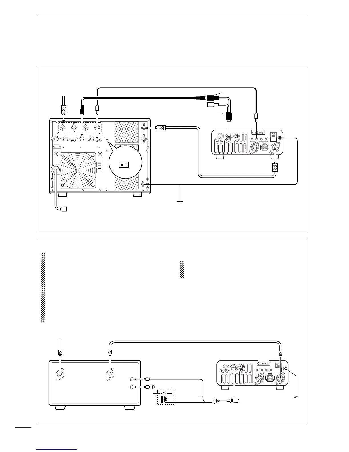
■ Linear amplifier connections
Use the [ANT1] connector when connecting an HF/50
MHz linear amplifier.
CONNECTING THE IC-PW1/EURO
To a n
antenna
ACC-1
ANT
ANT1
ACC
INPUT1
REMOTE
EXCITER
1
1&2
GND
GND
IC-PW1/EURO
AC outlet
Non-European versions : 100–120/220–240 V
European version : 230 V
Ground
Transceiver
REMOTE
Remote control cable (supplied with the IC-PW1/EURO)
ACC cable (supplied with the IC-PW1/EURO)
Coaxial cable
(supplied with the IC-PW1/EURO)
7-pin side
OPC-599 conversion cable
()
CONNECTING A NON-ICOM LINEAR AMPLIFIER
R WARNING:
•Set the transceiver output power and linear ampli-
fier ALC output level referring to the linear ampli-
fier instruction manual. Be sure the linear ampli-
fier keying circuit control voltage is compatible
with the IC-7000, before connecting to HSEND
line (ACC cable).
•The ALC input level must be in the range 0 V to
–4 V, and the transceiver does not accept positive
voltage. Non-matched ALC and RF power settings
could cause a fire or damage the linear amplifier.
•The IC-7000 SEND relay is rated at 16 V and a
0.5 A DC. If these levels are exceeded, a larger
external relay must be used.
 Loading...


