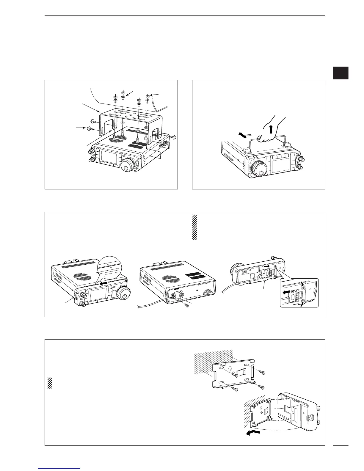
D Front panel separation
D Front panel mounting
q While pulling the front panel latch towards you,
slide the front panel to the left (fig. 1).
w Attach the optional OPC-1443 to the main body
and tighten the supplied screw as in fig. 2.
e Attach the other end of the OPC-1443 to the de-
tached front panel as in fig. 3.
CAUTION: NEVER detach/attach the front panel
when connecting the DC power supply (or battery).
Be sure to disconnect the DC power cable from the
[13.8 V] socket on the transceiver rear panel.
q Attach the MB-105 to a flat surface using the four
supplied screws (fig. 1).
w Fix the detached front panel to the MB-105 as il-
lustrated in fig. 2.
BE CAREFUL to mount the MB-105 so that the
front panel attaches with the correct side up.
fig. 1
fig. 2 fig. 3
fig. 1
fig. 2
To raise the stand:
With the transceiver upside down, pull the stand to-
wards the rear panel and then upwards, as illus-
trated below.

 Loading...


