87
15
OPTION UNIT INSTALLATIONS AND SETTINGS
■ IF filter
Several IF filters are available for the IC-703. Choose
a filter most appropriate to your operating needs.
NOTE: After filter installation, specify the installed
filter using initial set mode (item 22, p.79). Other-
wise, the installed filter will not function properly.
FL-52A
CW
/
RTTY NARROW FILTER
500 Hz/–6 dB
FL-53A
CW NARROW FILTER
250 Hz/–6 dB
FL-222
SSB NARROW FILTER
1.8 kHz/–6 dB
FL-257
SSB WIDE FILTER
3.3 kHz/–6 dB
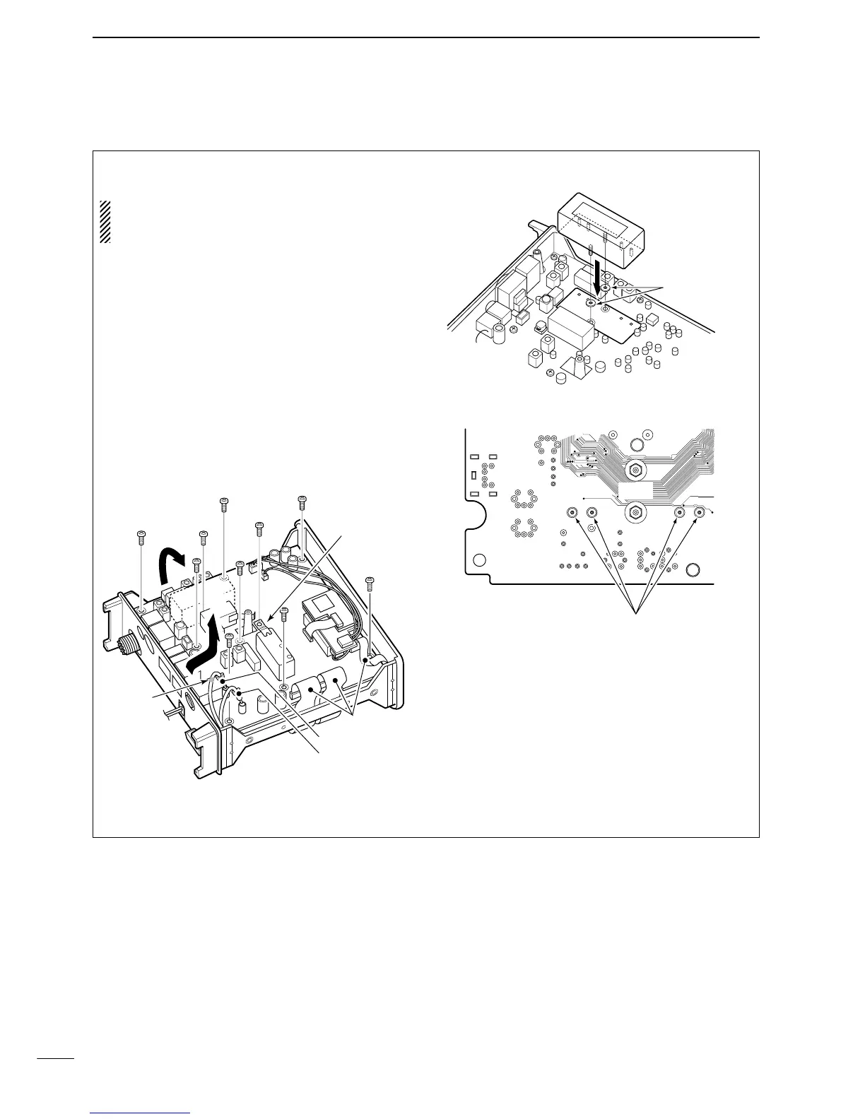
q Remove the top cover as shown on the previous
page.
w Disconnect the coaxial cable connectors, P2 and
P4, then unscrew 10 screws on the MAIN unit.
•Attach the grounding spring at the same place when re-
turning.
e Slide the MAIN unit in the direction of the arrow q,
then open the MAIN unit in the direction of the
arrow w.
• Be careful for the flat cables.
r Install the desired filter as shown in the diagram
below.
t Tighten the nuts then solder the filter’s pins.
y Return the MAIN unit to the original position.
•Make sure to attach the grounding spring to the original
position.
u Connect P2 and P4 to J2 and J1, respectively.
i Replace the top cover.

 Loading...


