55
6
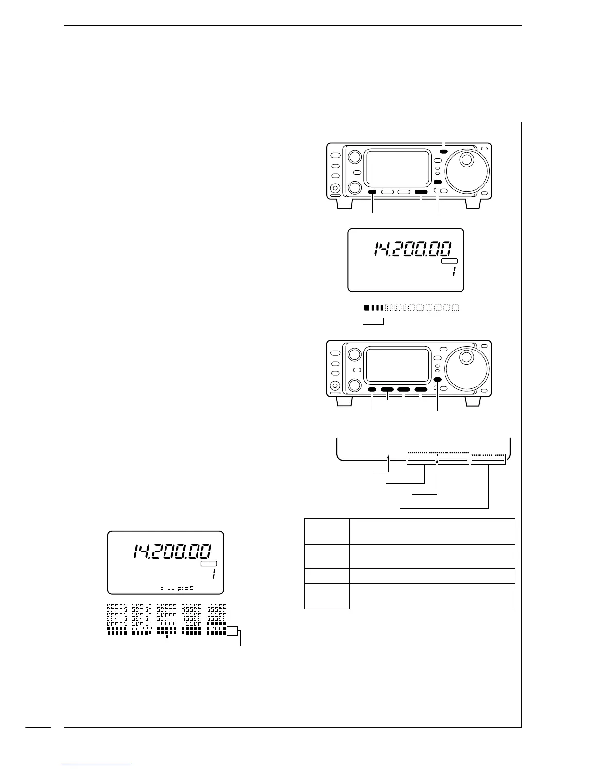
FUNCTION FOR TRANSMIT
The IC-703 has a built-in circuit for measuring an-
tenna SWR—no external equipment or special ad-
justments are necessary.
The IC-703 can measure SWR in 2 ways:
(A) Spot measurement; or (B) Plot measurement.
(A) Spot measurement
q Confirm that the output power is over 5 W.
w Push [MENU] one or more times to select M3.
e Push [(F-3)MET] to select the SWR meter.
r Push [MODE] one or more times to select CW or
RTTY operation.
•Key down or push [PTT] to transmit; then read the ac-
tual SWR from the meter:
➠ ≤ 1.5 well matched antenna
➠ > 1.5 check antenna or cable connection, etc.
(B) Plot measurement
Plot measurement allows you to measure the SWR
over an entire band.
q Confirm that the output power is over 5 W.
w Push [DISPLAY] once or twice to select G.
e Push [MENU] one or more times to select G2.
r Set the center frequency for the SWR to be mea-
sured.
t Push and hold [
(F-1)
10k] one or more times to se-
lect the desired frequency pitch.
y Push and hold [
(F-2)] one or more times to select
the desired step.
u After selecting the desired pitch and step, push
[
(F-3)STR] to measure the SWR.
• RTTY mode is selected automatically.
i Push and hold [PTT] to display the SWR in a bar
graph readout.
o When [PTT] is released, the frequency marker and
frequency indication move to the next frequency to
be measured.
!0 Repeat steps i and o to measure SWR over the
entire frequency range.
!1 When the measured SWR is less than 1.5, the an-
tenna is well matched.
■ SWR
D Measuring SWR
Span
Push [F-1] for 1 sec. to change the se-
lected span.
Step bar
Push [F-2] to change the step bar (3, 5,
7 or 9 steps are available.
Marker Indicates the currently active step bar.
Start
Flashes while the SWR is being mea-
sured.

 Loading...


