2
12
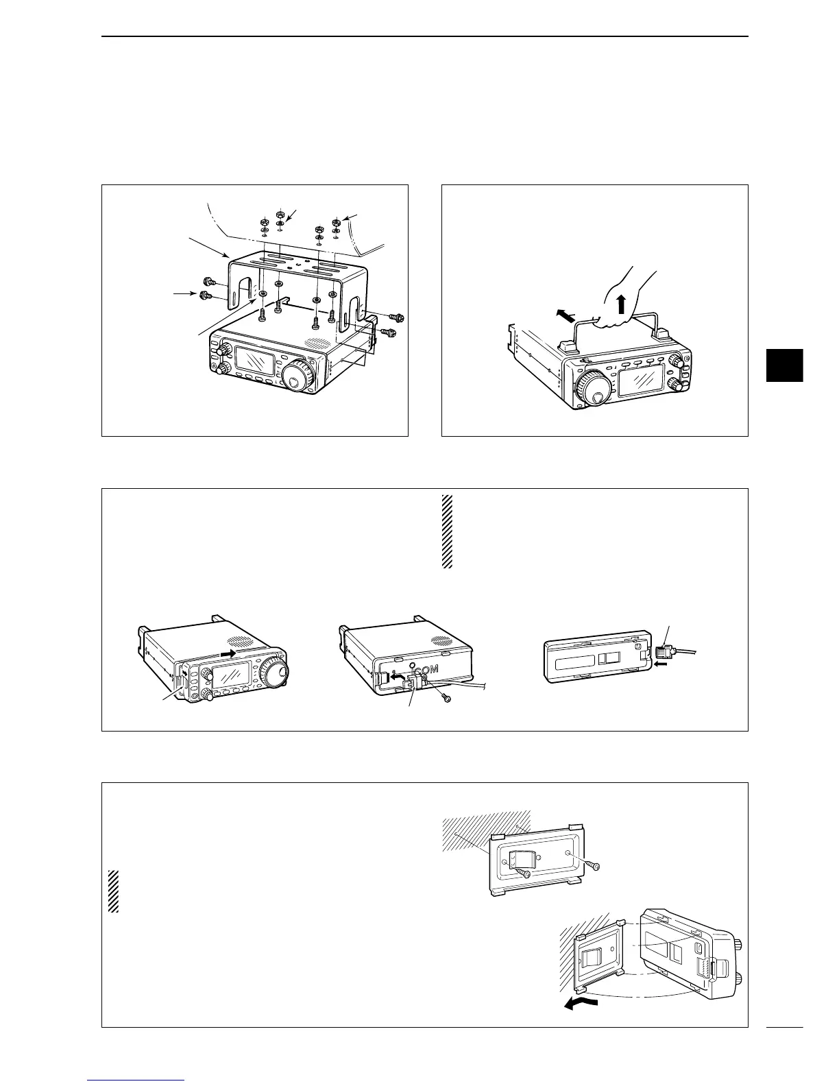
INSTALLATION AND CONNECTIONS
To raise the stand:
With the transceiver upside down, pull the stand to-
wards the rear panel and then upwards, as illus-
trated below.
■ Installation
D Single body mounting D Stand
D Front panel separation
D Front panel mounting
q While pulling the panel release button towards you,
slide the front panel to the right (fig. 1).
w Attach the optional OPC-581 to the main body and
tighten the supplied screw as in fig. 2.
e Attach the other end of the OPC-581 to the de-
tached front panel as in fig. 3.
CAUTION: NEVER detach/attach the front panel
when connecting the DC power supply (or battery).
Make sure the disconnecting DC power cable from
the [13.8 V] receptacle on the transceiver rear
panel.
q Attach the MB-63 to a flat surface using the two
supplied screws (fig. 1).
w Fix the detached front panel to the MB-63 as illus-
trated in fig. 2.
BE CAREFUL of the orientation of the MB-63, oth-
erwise, the front panel may become attached in the
opposite direction.

 Loading...


