2
1
PANEL DESCRIPTION
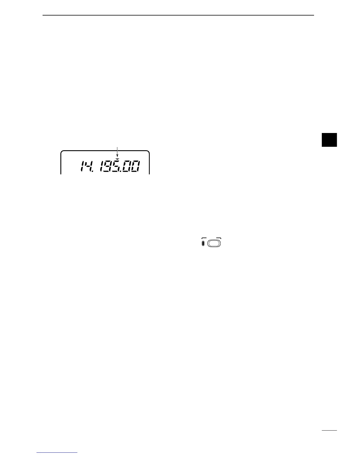
r FUNCTION DISPLAY
Shows the operating frequency, dot matrix indica-
tions, selected memory channel, etc. See p. 9 for
details.
t TUNING STEP SWITCH [TS] (pgs. 19–21)
➥ While in SSB/CW/RTTY modes, push momentar-
ily to turn the programmable tuning step ON and
OFF. While in FM/AM mode push momentarily to
toggle the programmable tuning step and 1 MHz
quick tuning step.
•While the programmable tuning step indicator is dis-
played, the frequency can be changed in programmed
kHz steps.
•0.01 (FM/AM mode only), 0.1, 1, 5, 9, 10, 12.5, 20, 25
and 100 kHz tuning steps are available.
•1 MHz quick tuning step are only available in FM and
AM modes.
➥ While the programmable tuning step is OFF, turns
the 1 Hz step ON and OFF when pushed for 1
sec.
•1 and 10 Hz steps are only available in SSB, CW and
RTTY modes.
•1 Hz indication appears, and the frequency can be
changed in 1 Hz steps.
➥ While the programmable tuning step is ON, en-
ters the tuning step selection mode when pushed
for 1 sec.
y MODE SWITCH [MODE] (p. 23)
➥ Push momentarily to cycle through the operating
modes:
USB/LSB ➧ CW ➧ RTTY/SSB-D ➧ FM/AM
➥ Push for 1 sec. to toggle the following operating
modes:
USB ↔ LSB
CW ↔ Memory keyer mode
RTTY↔ SSB-D (SSB data mode)
FM ↔ AM
u RECEIVE/TRANSMIT INDICATORS [RX]/[TX]
➥[RX]: Lights green while receiving a signal and
when squelch is open.
➥[TX]: Lights red while transmitting.
i MAIN DIAL
Changes the displayed frequency, sets the values
of selected initial set mode items, etc.
o UP/DOWN (BAND) SWITCHES [Y/Z(BAND)]
➥ Push momentarily to select a band.
•Can also be used to advance or back the quick set
mode items, initial set mode items, etc.
➥ Push and hold to scroll through the bands contin-
uously.
!0 MAIN DIAL TENSION LATCH
Selects the main dial tension.
• 2 positions are available.
!1 MICROPHONE CONNECTOR (p. 10)
Modular-type microphone connector—Accepts the
supplied microphone (HM-103).
•The optional OPC-589 can be used to connect an 8-pin
microphone such as the SM-8 or SM-20, if desired.
•A microphone connector is also available on the rear
panel. DO NOT connect 2 microphones simultaneously.
!2 LOCK SWITCH [LOCK]
➥ Push momentarily to toggle the dial lock function
ON and OFF.
•The dial lock function electronically locks the main
dial.
➥ When the optional UT-102
VOICE SYNTHESIZER
UNIT
is installed (p. 86), push for 1 sec. to have
the frequency, etc. announced.
•UT-102 operation can be adjusted in the initial set
mode (p. 82).
!3 DISPLAY SWITCH [DISPLAY] (p. 94)
➥ Push momentarily to select one of the three menu
sets: M1 to M4, S1 to S4 and G1 to G4.
➥ Push for 1 sec. to enter the quick set mode.
!4 MULTI-FUNCTION SWITCHES [F1] / [F2] / [F3]
➥
Push to select the function indicated in the dot ma-
trix display above these switches. (pgs. 4–6, 94)
• Functions vary depending on the menu set selected.
➥Push to edit a character for memory keyer pro-
gramming or memory name. (pgs. 35, 59)
!5 MENU SWITCH [MENU] (p. 94)
➥ Push this switch one or more times to select
menus within a menu set (M, S or G), or push to
advance through the quick set mode and initial
set mode displays.
➥ Push for 1 sec. to jump between two different
function menu sets.

 Loading...


