68
9
CONNECTIONS AND INSTALLATION
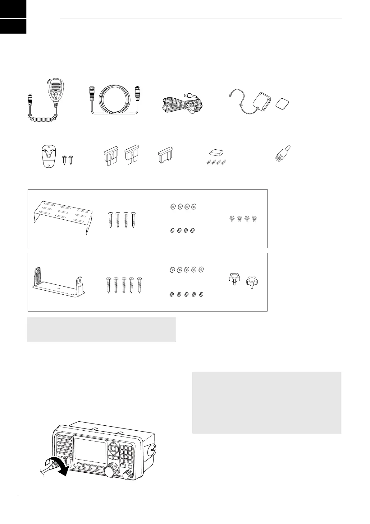
■ Supplied accessories
Microphone DC power cableRemote control cable
(5.1 m, 16.7 ft)
Mounting bracket kit for the remote controller
Mounting bracket Self-tapping screws (M5) Spring washers (M5)
Flat washers (M5)
Knobs
GPS antenna and
double-sided adhesive pad
Microphone hanger and
screws (3 × 16 mm)
Spare fuse
(ATC 30A)
Spare fuse
(BFLP 5A)
Accessory connector
(8-pin DIN)
Tuner connector kit
Mounting bracket Self-tapping screws (M5) Spring washers (M5)
Flat washers (M5)
Screws (M5)
Mounting bracket kit for the main unit
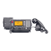
D Connecting the microphone
1. Insert the microphone’s connector into the
microphone jack on the remote controller’s front
panel.
2. Rotate the connector clockwise until it is
completely tightened.
CAUTION:
• Be sure that the microphone’s connector is
screwed in completely. Otherwise, the remote
controller may lose its waterproof protection.
• DO NOT use non-Icom microphones. Other
manufacturer’s microphones have di erent pin
assignments, and connection to the remote
controller may damage it.
Microphone’s
connector
■ Connections
NOTE: Some accessories are not supplied, or the
shape is di erent, depending on the transceiver
version.