78
9
CONNECTIONS AND INSTALLATION
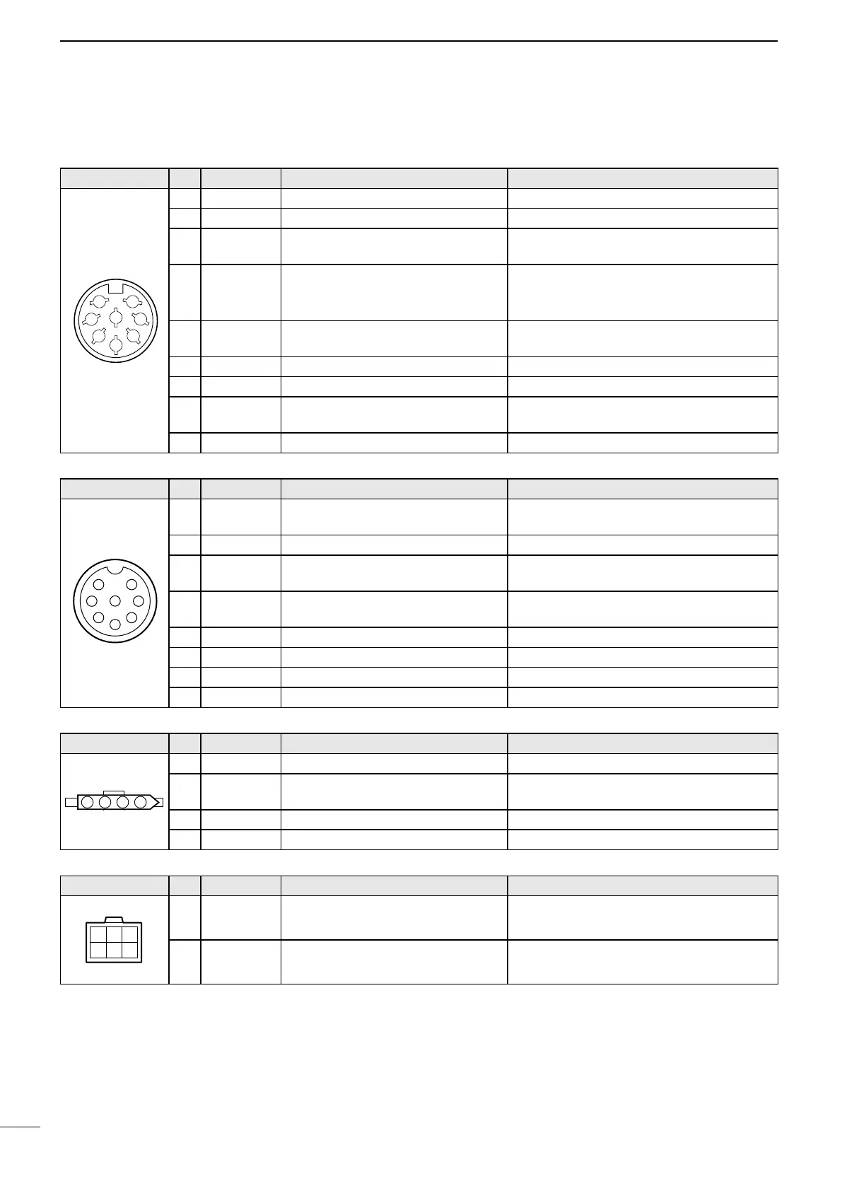
■ Connector information
ACC Pin Pin name Description
1 CWK
CW and FSK keying input. Input level: –0.5 to 0.8 V
2 AF GND
Ground line for AF signal. –
3 SEND
Input/Output pin.
Ground this pin to transmit.
Ground level: –0.5 to 0.8 V
Input current: Less than 20 mA
4 MOD
Modulator input.
Usable when pin 3 is grounded.
Input impedance: More than 10 kΩ
Input level: Approximately
100mV rms
5 AF
AF detector output.
Fixed, regardless of [VOL] position.
Output impedance: Less than 4.7 kΩ
Output level: 100–300 mV rms
6 NC
No connection. –
7 13.6 V
13.6 V output when power is ON. Output current: Maximum 1 A
8 ALC
ALC voltage input. Control voltage: –3 to 0 V
Input impedance: More than 10 kΩ
* DC GND
Common ground. –
MICROPHONE Pin Pin name Description
1 MIC+
Audio input from the microphone
element.
Input impedance: 1.74 kΩ ± 20 %
2 NC
No connection. –
3 AF1
AF output controlled with [VOL].
Connected to pin 4 in the microphone.
–
4 AF2
AF input.
Connected to pin 3 in the microphone.
–
5 PTT
PTT switch input. When grounded, transmits.
6 GND
Connected to the ground. –
7 MIC–
Coaxial ground for MIC+. –
8 AF–
Coaxial ground for AF1 and AF2. –
TUNER Pin Pin name Description
1 KEY
Key signal input. –0.5 to 0.8 V during tuning.
2 START
Start/Through signal output. Pulled up 8 V, 0 V (100 msec) as a start
signal.
3 13.6 V
13.6 V output. Maximum current: 2 A
4 E
Negative ground. Ground terminal for above signals.
DC 13.6 V Pin Pin name Description
1–3
DC input
.
Maximum power consumption:
30 A typical.
4–6
DC input
.
–
1
2
3
4
5
6
7
8
y
t
r
q
w
e
i
u
4321
12
3
5