WindO/I-NV4 User’s Manual 33-5
1 Bit Devices
33
Internal Devices
1.2 Control Device Addresses
■ Expansion Inputs (#I)
Device addresses that input on/off information from external devices to the MICRO/I. Input Relay for digital I/O
module connected to HG5G/4G/3G/2G-V and BACnet communication.
For details, refer to Chapter 30 “2.1 Using Digital I/O Modules” on page 30-12 and Chapter 3 “7 BACnet
Communication” on page 3-94.
■ Expansion Outputs (#Q)
Device addresses that output on/off information from the MICRO/I to external devices. Output Relay for digital I/O
module connected to HG5G/4G/3G/2G-V and BACnet communication.
For details, refer to Chapter 30 “2.1 Using Digital I/O Modules” on page 30-12 and Chapter 3 “7 BACnet
Communication” on page 3-94.
■ Internal relays (#M)
This is a bit-unit device for the BACnet communication.
For details, refer to Chapter 3 “7 BACnet Communication” on page 3-94.
*1 The last digit of the address number is 0 to 7 in octal notation.
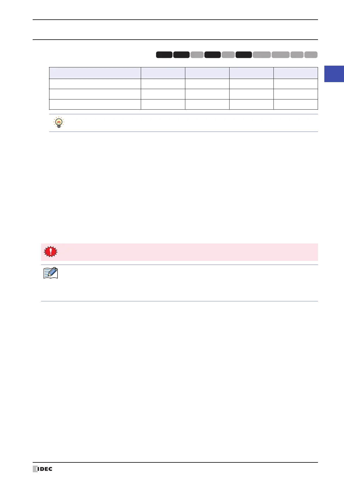
Device Name Symbol R/W Address Range Base
Expansion Inputs #I R 30 to 107
10
*1
Expansion Outputs #Q R/W 30 to 127
10
*1
Internal relays #M R/W 0 to 797
10
*1
HG3G
HG2G-5FHG5G-V HG4G-V HG3G-V HG2G-V HG2G-5T
HG4G HG1G HG1P
R/W is an abbreviation of Read/Write. R/W indicate that both reading and writing are possible, while R
indicates that only reading is possible.
All values of the control device addresses becomes 0 at the start of operation.
When entering the control device, inputs "#" before the symbol (device type). In addition, on the Device
Monitor a "#" is displayed before the symbol.
Example: I100 is configured.
#I100
 Loading...