FC6A S
ERIES
M
ICRO
S
MART
A
LL
-
IN
-O
NE
T
YPE
U
SER
’
S
M
ANUAL
FC9Y-B1722 2-83
2: P
RODUCT
S
PECIFICATIONS
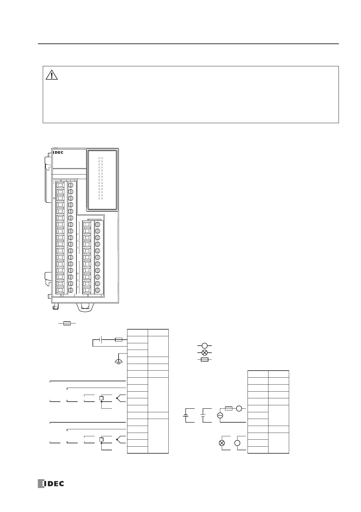
Terminal Arrangement and Wiring Examples
■ FC6A-F2M1, FC6A-F2MR1
*1 OUT0: Relay output and OUT1: Non-contact voltage/current output connection examples are shown. There are no models with both types of
specifications.
• When connecting the terminal, insert an IEC 60127-approved fuse suitable for the applied voltage and current draw at
the position shown in the following diagram.
This is required when equipment containing the MicroSmart is destined for Europe.
• Do not connect a thermocouple to a part with hazardous voltage (60V DC or peak 42.4V DC or higher part).
• Before turning on the power, always check the wiring. If the wiring is incorrect, the PID module may be damaged.
• When connecting stranded wire or multiple wires to a terminal block, always use a ferrule for the terminal block.
For details, see "Recommended Ferrule List" on page 3-35.
Terminal block type Applicable Connector: FC6A-PMTC11PN02, FC6A-PMTC17PN02
FC6A-F2M1
NC I1- I1+ I1+’ I1+’’ NC NC I0- I0+ I0+’ I0+’’ NC NC NC 0V 24V
Q1- NC Q1+ NC Q0- NC Q0+ NC NC NC NC
B’ B A RTD B’ B A RTD
OUT0
EVT0
AT0
MT0
F/P0
R/H0
R/L
OUT1
EVT1
AT1
MT1
F/P1
R/H1
PWR
PID
+
–
L
+–
+
–
TC
A
RTD
B
B
+
–
0 to 1 V
DCDC
0 to 5 V
1 to 5 V
0 to 10 V
+
–
+
–
DC
0 to 20 mA
4 to 20 mA
+
–
TC
A
RTD
B
B
+
–
0 to 1 V
DCDC
0 to 5 V
1 to 5 V
0 to 10 V
+
–
+
–
DC
0 to 20 mA
4 to 20 mA
: Fuse (50 V-1.2 A) : Voltage/current
: Resistance Thermometer
: Thermocouple
DC
RTD
TC
: Load
: Analog Current Input Device
: Fuse
L
L
24V
GND
FG
NC
NC
NC
+”
+’
A +’
B’ –
B
NC
+”
+’
A +’
B’ –
B
Terminal No.
I/O
24V DC
IN 1
–
IN 0
–
–
–
NC
NC
Terminal No.
I/O
OUT 1
–
–
+
NC
NC
NC
NC
NC
–
+
OUT 0
–
–
–
–