C-COM Satellite Systems Inc. Page 33 of 164
7.6.1.1. MAIN
This branch menu displays the real-time Elevation, Azimuth, Polarization Angles, their
respective limits (Up, Down, Stow), the RF Receive Signal, Signal Strength, and the
System Status.
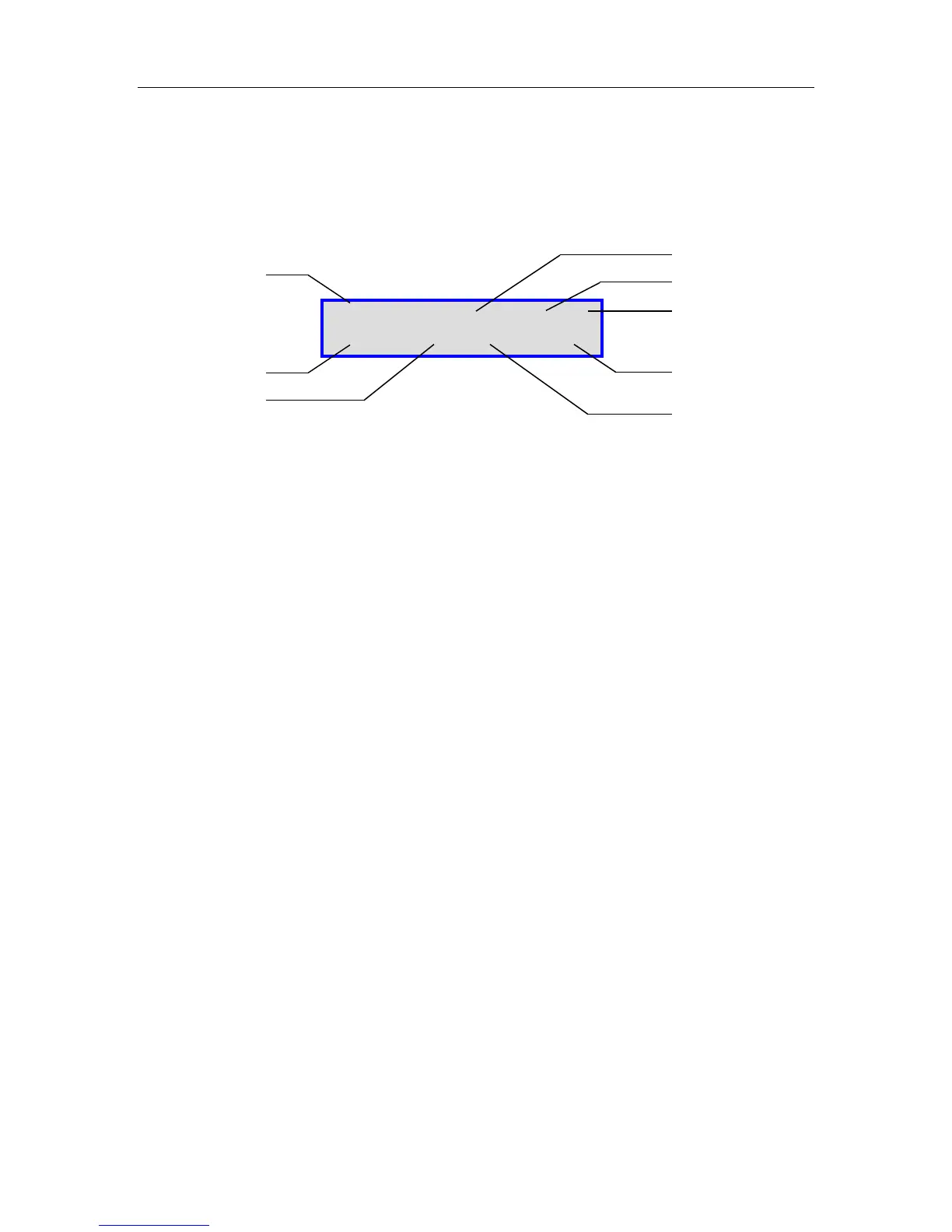
Fig. 18: “MAIN” (Main) Display
1 – Elevation Angle and Limit Indicators
740/750/950/980 Mobile Platform Range: -90 to 65+
981/985/755 Drive-away Platform Range: -90 to 93+
1200/1500/1800 Mobile Platform Range: -90 to 76+
Flyaway Antenna (1200Q) 5 to 78+
Airline Checkable (1210A) 9 to 99+
1201 Drive-away -90 to 93+
Elevation Angle will be –90.0 when the Elevation Stow Indicator is ON for mobile/drive-away units
U Elevation up Limit has been reached.
Typically set above 75 for 1200/1500/1800 Mobile Platforms, above 65 for 740/950/980
Mobile Platforms, and above 90 for the 1201/985/755 Drive-away Platforms. The Flyaway
is set above 78.
D Elevation down Limit has been reached.
Typically set between 5 and 10 for 1200/1500/1800 Mobile Platforms and between 0
and 10 for 740/950/980 Mobile Platforms.
S Elevation Stow Limit has been reached.
2 – Azimuth Angle and Stow Limit Indicator
Range: -200 to +200
Flyaway Range: -180 to +180
Airline Checkable: -195 to +195
S Azimuth Stow Limit has been reached.
Mobile Platform should be physically centered on the Azimuth axis.
E-90.0 U D S A -45.7 S VV ST
P-34.6 S 30N M140D 0U