C-COM Satellite Systems Inc. Page 76 of 164
Antenna will move to the target Elevation, Polarization, and Azimuth for reading
the compass heading such that the user can determine if the compass reading is
accurate at that point.
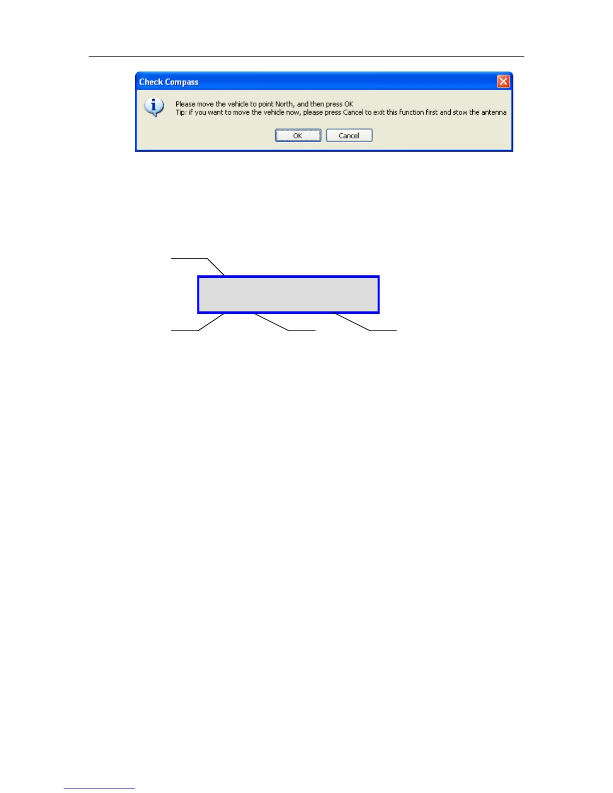
7.6.5.5. CP
1 – RF Search Mode Status (values displayed but not used for CP tests/calibrations)
N RF Mode is disabled; Y will be displayed when enabled.
N RF override mode is disabled; O will be displayed when enabled.
RF Threshold (55) Value will be displayed here, this value is configurable.
RF/DVB signal value (30N) – If in RF search mode this will represent RF signal value, if in DVB
Mode it will display DVB carrier signal. The letter ‘N’ next to the
RF Value indicates the LNB is not being powered properly.
The letter “L” next to the value indicates a DVB signal LOCK.
2 – Compass Status
V – Valid
O – Override
F - Failed
3 – Compass Heading
Compass Heading after Compass has been read.
Approximate Headings: North 354
East 87
South 176
West 265
Compass Accuracy Readings
Tests the compass’ heading and accuracy by rotating the antenna at 90
intervals and comparing the compass readings with the actual antenna’s
movement.
RF :N-N-55-30N
CP:V-0 AZ_W :60