1 - 22
Transpector XPR 3+ Operating Manual
1.16.6 Electronics Module Installation
Transpector XPR 3+ electronics module must be mounted in an area where the
ambient temperature does not exceed 50°C and there is free air circulation around
the electronics module. Best performance will be achieved if the electronics
module is not located close to major heat sources where it is subjected to wide
temperature variations. (See Figure 1-19.)
After the sensor has been installed on the vacuum system, the
Transpector XPR 3+ electronics module must be mounted on the sensor:
1 The Transpector XPR 3+ sensor mounting connector assembly includes a
mounting nut, a flat teflon ring, and an O-ring. When the mounting nut is
tightened, the O-ring compresses making a tight fit on the sensor housing. For
proper installation, place the nut over the end of the sensor and roll the O-ring
back to the groove on the sensor.
2 Note the alignment pin or key pin and match the sensor feedthrough to the
electronics module and carefully slide the Transpector XPR 3+ module onto the
sensor. Ensure the Transpector XPR 3+ electronics module slides on fully.
3 Hand tighten the mounting nut on the Transpector XPR 3+ sensor.
4 Continue to section 1.16.8 and install the communications cable.
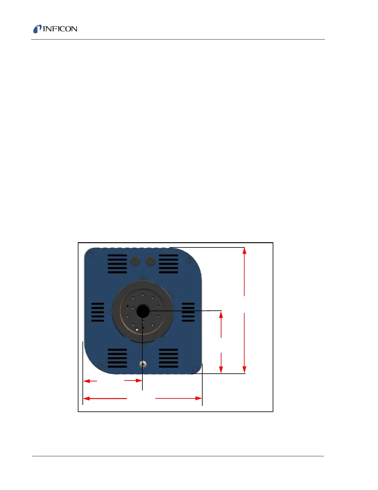
Figure 1-19 Electronics module dimensions
121.67 mm
60.32 mm
57.48 mm
114.96 mm
(4.79 in.)
(2.375 in.)
(2.263 in.)
4.526 in.