1 - 17
Transpector XPR 3+ Operating Manual
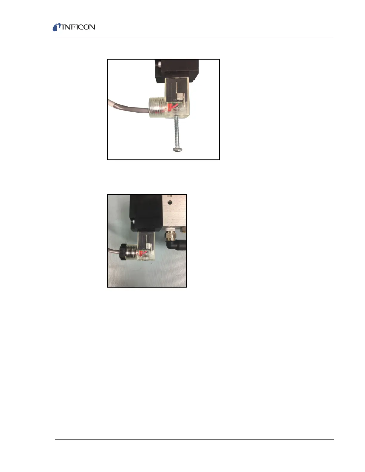
Figure 1-15 Connecting the connector
8 Screw the assembly back into the solenoid coil using the screw (8) removed in
step 1.
Figure 1-16 Screw the assembly back into the solenoid coil
1.16.3 Mounting the Pirani Interlock Weldment Assembly
Transpector XPR 3+ Interlock Weldment Assembly with a Pirani gauge port has a
1.5 in. (38 mm) inner diameter for the Transpector XPR 3+ sensor. Both CF-40
flanges rotate to provide flexibility in orientation of the Pirani gauge with respect to
the Transpector electronics module, the isolation valve, and the tool.
1 Evaluate, or pre-fit, Transpector XPR 3+ on the tool port to determine the
orientation of the Transpector electronics module with respect to the tool, and
the Pirani gauge with respect to a side of the Transpector electronics module.
Typically, the Pirani gauge is placed under the Transpector electronics module
if the axis of Transpector XPR 3+ is horizontal, as shown in Figure 1-17.
NOTE: For measurements of 2x10
-2
Torr or less, that are involved in protection
of the Transpector XPR 3+ filament, the Pirani gauge retains its
accuracy in any orientation.