Multitron - Operating Manual
Setup and Function
20 August 2020 Page 29 of 158
3.3 Connections and Interfaces
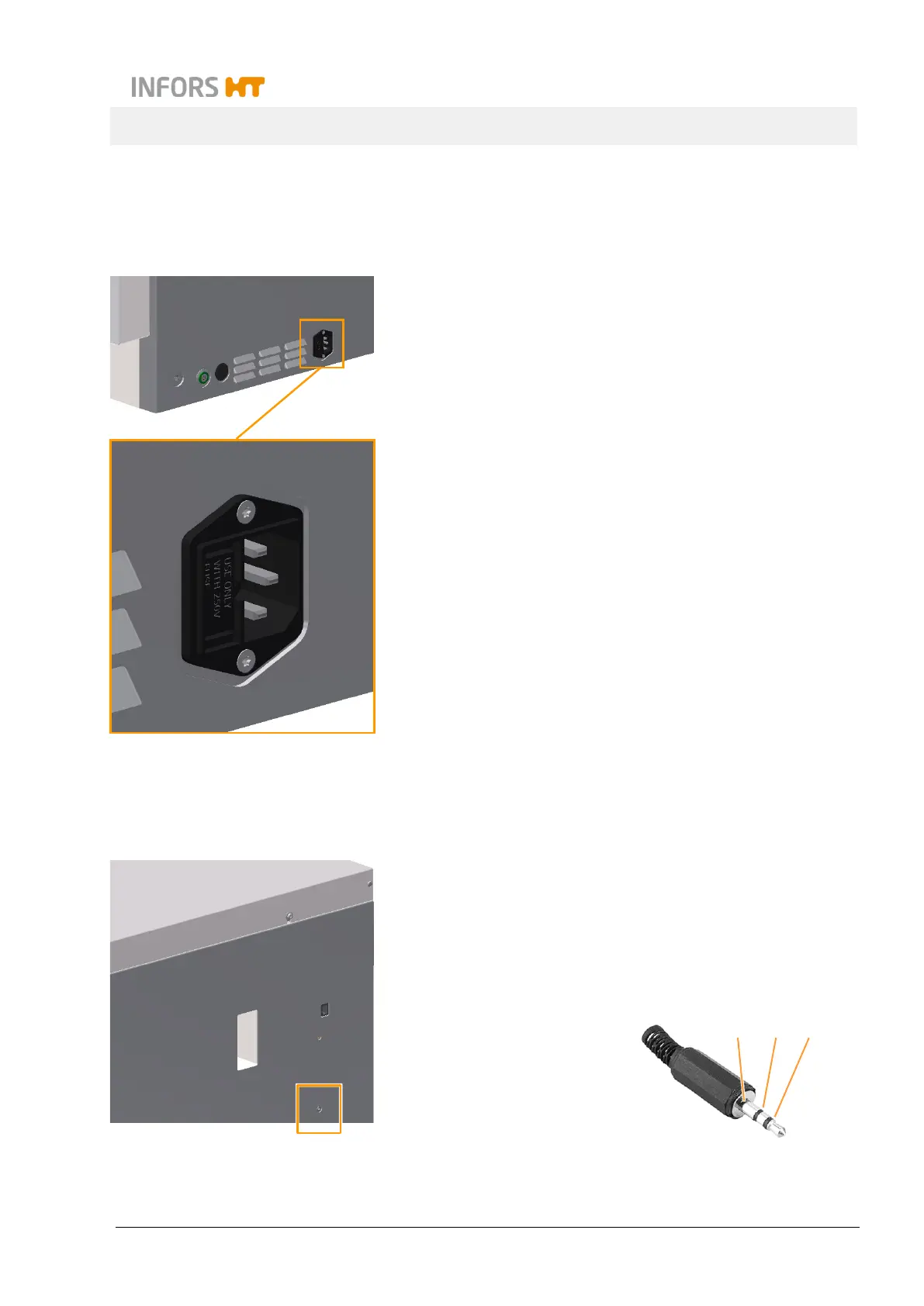
3.3.1 Mains Connection
The mains connection is located on the right side of the device. Three
different versions of the device are available for different mains volt-
ages:
230 V 50 Hz
230 V 60 Hz
115 V 60 Hz
Two fuses (230 V version) or two thermal protection switches (115 V
version) immediately adjacent to the power connection protect the
device from impermissibly high power input.
The country-specific power cable required for connecting the device
to the ma
ins is included in the device’s scope of delivery. If the power
cable is defective, replace it with a power cable of the same type.
Prior to connecting the device, make sure that the connecting values
of the device match those of the local power supply. The mains con-
nection must be easily accessible at all times so that the device can be
disconnected from the power supply quickly in case of an emergency.
For information on the electrical connection values, see chapter 12.3
"Specifications of the Basic Unit", page 140.
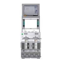
3.3.2 Alarm Connection
On the right side of the casing there is a socket (stereo jack, 3.5 mm)
for connecting the device to an alarm system. It is labelled
ALARM
EXTERN
. The socket is designed for a maximum of 34 V AC/DC, 1 A.
The alarm relay is permanently activated as long as
(not toggling).
Allocation of contacts
1 COM (common)
2 NC (normally closed)
3 NO (normally open)
1
3
2