A HARDWARE REFERENCE
3-3
3.2 CPU MODULES
As shown in Figure 3-1, a CPU module is a smaller board that attaches directly onto the Cyclone EP.
Several CPU modules are available — one for each member of the i960 processor family. Each module
contains a i960 processor, boot Flash ROM with the MON960 monitor, appropriate glue logic and
configuration switches.
3.2.1 CPU Module Installation
CPU modules are easy to install when a few guidelines are observed:
• Make sure the power is OFF before you install or remove a CPU module.
• Do not “peel” connectors. Peeling is the action of lifting one end of the connector before the
other. This can bend or break the pins and connectors.
3.2.2 CPU Module Clock Frequencies
The CPU modules have user-assignable clock frequencies. Make sure you do NOT select a frequency
faster than the installed processor is capable of running. Table 3-2 outlines the processor frequency
switch settings. It is recommended that you remove power before you change the switch settings;
however, if you change the switch settings while power is connected, press the reset switch to reboot the
processor at the new frequency.
NOTE:
DO NOT select a frequency faster than the installed processor is capable of running.
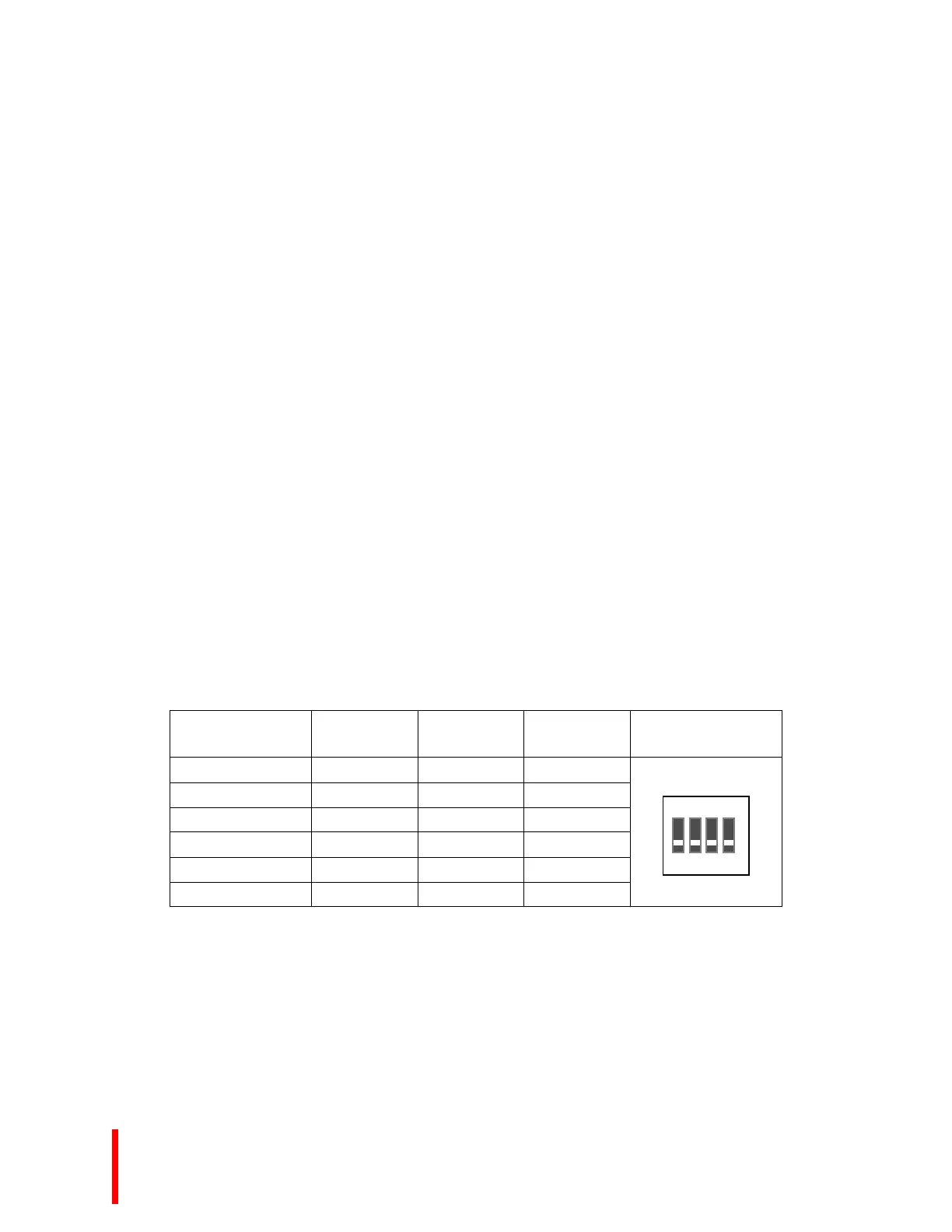
Table 3-2. CPU Module Frequency Switch Settings
Frequency
FREQ2
(Pos2)
FREQ1
(Pos3)
FREQ0
(Pos4)
Switch Diagram
1,2
16 MHz ON OFF ON
20 MHz ON OFF OFF
25 MHz OFF ON ON
33 MHz OFF ON OFF
40 MHz OFF OFF ON
50 MHz OFF OFF OFF
NOTES:
1. On the 80960Sx and Kx CPU Modules, the CPU Module Frequency Switch is labeled SW2. On all other
80960 CPU Modules, the CPU Module Frequency Switch is labeled SW1.
2. CPU module switch position 1 (Pos1) is the V
PP
switch. It is recommended that you leave it OFF. (Factory
default position.)
O F F
1 2 43