SQUALL II MODULE INTERFACE A
5-12
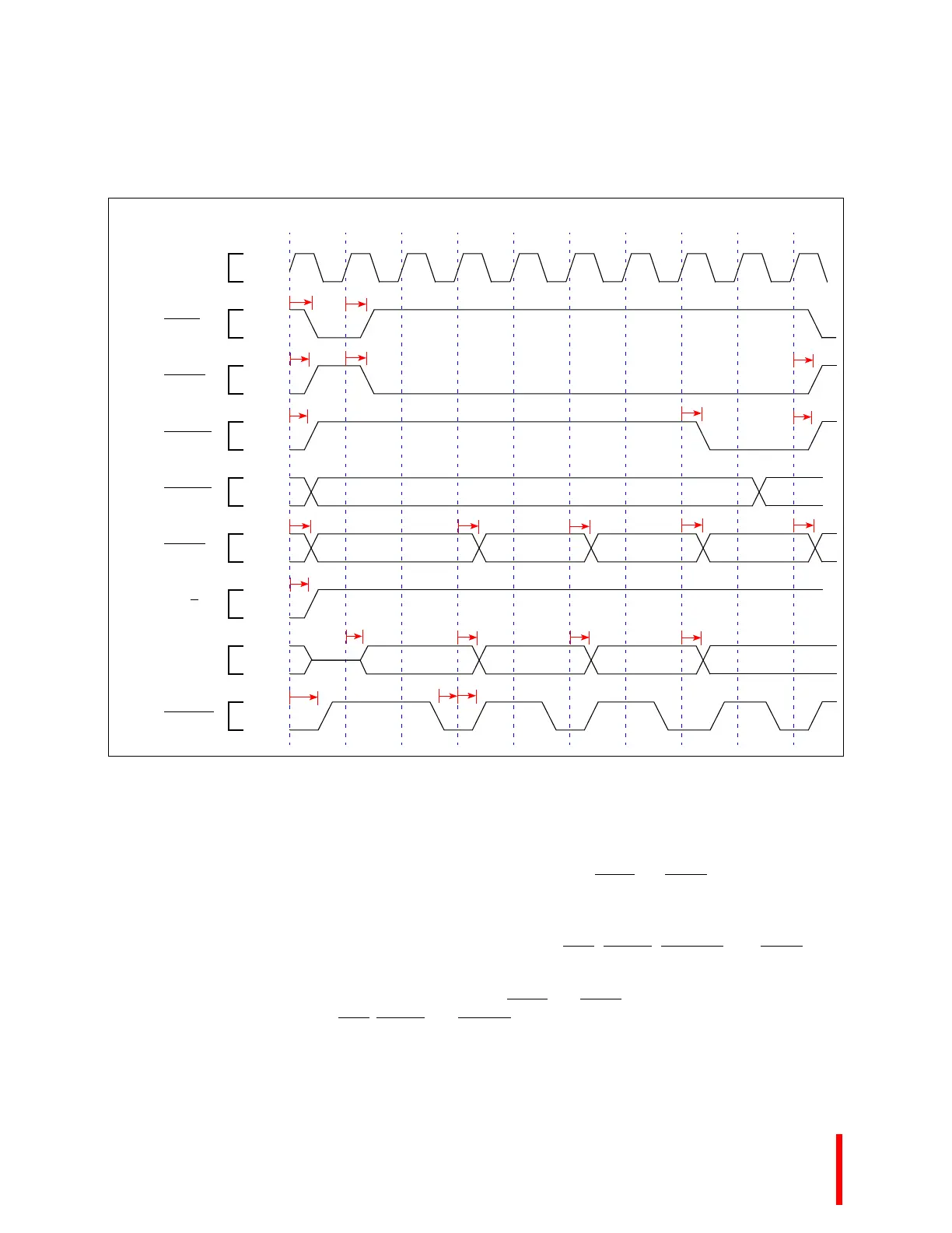
Figure 5-6. Squall II Slave Burst Write Timing Diagram
5.6.2 Squall II Module Master Timing
Squall II Module circuits may become masters of the shared bus to perform DMA operations to the
shared DRAM. DMA controllers gain control of the bus via the SQBR
and SQBG signals.
All signals, except the interrupt signals, are synchronous to the processor's clock (PLCK). Set up and
hold times must be observed for every rising clock edge. Because of the high clock rates, the following
signals must be driven high before they are three-stated: ADS
, BLAST, EXTEND, and LOCK. This
ensures that valid levels are observed on every rising clock edge.
DMA controllers gain control of the bus via the SQBR
and SQBG signals. Memory cycles may then
proceed with the same ADS
, BLAST, and READY protocol used by the i960 Cx, Jx, and Hx processors.
S_ADS
PMCLK
1 2 3 4 5 6 7 8 9 10
SQxSEL
S_BLAST
S_A[4:31]
S_A[2:3]
S_W/R
S_DATA
S_READY
t1
t1
t2
t2
t2
t6
t6
t6
t7
t7t7
t7t7
t8
t11
t11 t11
t11
t10
t10
t9