HARDWARE REFERENCE A
3-34
Example DMA configuration code is included in the PCI-SDK Platform diagnostics, which are
packaged with the board.
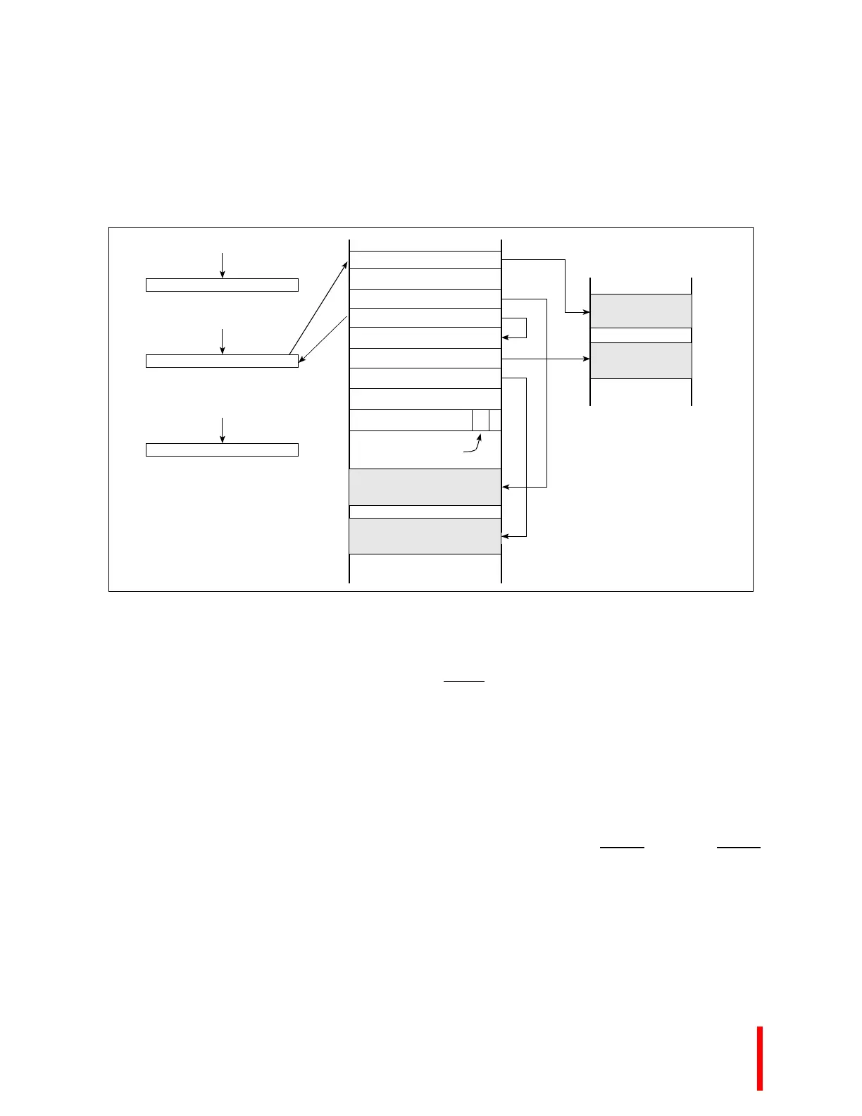
Figure 3-7. Chaining DMA Initialization
3.12.7.3 DMA Interrupts
DMA interrupts are signalled by the PCI 9060 (XINT0
on Cx, Hx, and Jx; INT2 on Sx and Kx). As with
all local PCI interrupts, DMA interrupts are controlled and detected through the Interrupt Control and
Status Register (E8H). To receive a DMA interrupt when a transfer is complete, software must set the
Local DMA Interrupt Enable bit for the channel in use, ensure that the PCI Local Interrupt Enable bit is
set, and set the Done Interrupt Enable bit in the DMA Mode Register for that channel. When a DMA
interrupt occurs, the Interrupt Control and Status Register (E8H) indicates the interrupt source. The
interrupt can be cleared by setting bit 3 of the DMA Command and Status Register (128H) for a channel
0 interrupt, or bit 11 for a channel 1 interrupt.
If a PCI master or target abort occurs while the DMA is transferring data, bit 25 or 26 of the Interrupt
Control and Status Register (E8H) is set. This condition also generates an LSERR
interrupt, if LSERR
is enabled in the Interrupt Control and Status Register (E8H).
Set DMA mode to chaining
Set up 1st Descriptor Pointer Register
(1st only requires Descriptor Pointer)
Setting the Enable and Go bits in the DMA
Command/Status Register initiates
the DMA transfer
Mode Register
Descriptor Pointer Register
Command/Status Register
1st PCI Address
1st Local Address
1st Transfer Size (byte count)
Next Descriptor Pointer
PCI Address
Local Address
Transfer Size (byte count)
Next Descriptor Pointer
End of chain
specification bit
1st Memory Block
to Transfer
Next Memory Block
to Transfer
PCI Host Memory
1st Memory Block
to Transfer
Next Memory Block
to Transfer