A
3-1
CHAPTER 3
HARDWARE REFERENCE
The location of the CPU and Squall modules, connectors, switches, and LEDs are described in this chapter. Also
covered are the memory maps, I/O and memory operation. For the PCI-SDK Platform, this chapter describes the PCI
9060 interface and operation.
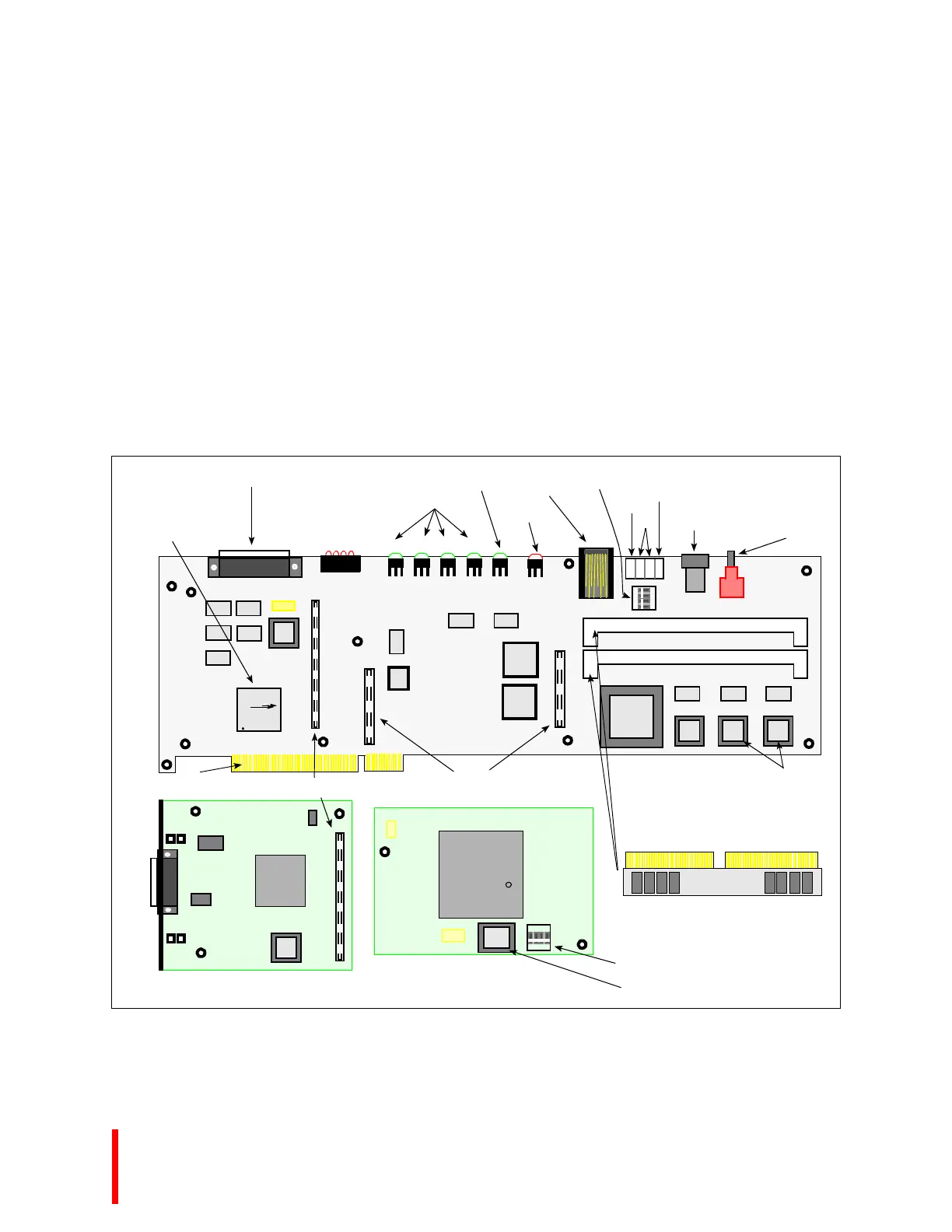
3.1 CONNECTORS, SWITCHES AND LEDS
Figure 3-1 shows the physical location of the components you need to understand to use the Cyclone
Evaluation Platform; Table 3-1 describes the function of each. For a complete list of components, refer
to APPENDIX A, PARTS LIST.
Figure 3-1. Cyclone EP and PCI-SDK Platform Physical Diagram
Squall II Module CPU Module
CR1
S1
CR2 CR3 CR4
CR5
CR6
J1
U20
J5
J6
S2
U19
i960®
A
i
XXXXXXXX A0
x80960xx-00
M
© 19xx
Xx Processor Module
CYCLONE MICROSYSTEMS
COPYRIGHT 1994
SW1
O F F
1 2 43
connectors on bottom of CPU module attach here
DRAM SIMM
CYCLONE MICROSYSTEMS
COPYRIGHT 1995
Rev. xxxx
123-1234-12
Z2
U5
U4
U2
U3
U1
J2
attach SIMMs in connectors at 45° angle
Z1
J7
J2
J3
J4
+5 VDC
+12 VDC
Four-Position
DIP Switch
RS-232
Serial Port
Reset
Pushbutton
Fail LED (red)
Power LEDs (green)
+5V +12V -12V +3.3V
Bus Cycle LED (green)
25-Pin Parallel Port
(Centronics compatible)
Flash Memory
Frequency and VPP switches
Flash Memory (MON960)
GND
+5 VDC
PLX
PCI 9060
flip squall module over Connect this edge connector
to your system’s PCI slot and attach connectors
PCI-SDK Platform
ONLY
CR9
User LEDs
(red)
0 1 2 3
Power Supplies
(Cyclone EP Only)
Connectors for external