A
5-1
CHAPTER 5
SQUALL II MODULE INTERFACE
Design information, electrical and physical specifications of the Squall II Module interface are described in this
chapter. This information is useful when you wish to design and integrate your own Squall Modules. If you are using
a standard Squall Module, refer to the specific module's manual for information on the operation of that module.
5.1 Physical Attributes
The Squall II Module is a printed circuit board which connects to the Cyclone EP. The physical
dimensions of the Squall II Module interface are illustrated in Figure 5-1, Squall II Module Component
Height Allowance and Figure 5-2, Squall II Module Dimensions. The Cyclone EP has a cutout on the
board along the front panel to provide more clearance for connectors mounted on the Squall II Module.
The Cyclone EP is designed to support one of several Squall II modules. These modules allow different
I/O interfaces to be used. Devices on the module may be accessed by the processor in slave mode.
Devices with DMA controllers on the Squall II Module may access the shared (packet) DRAM in
master mode. The Squall II Module has up to 3.3 inches of front panel space to accommodate I/O
signals and connectors.
Each Squall II Module contains a serial EEPROM which allows the processor to determine the type,
revision, and programming information of the specific module. The EEPROM is read via the Z8536
CIO device. Section 5.3 outlines the use of the EEPROM. Currently available Squall II Modules are
listed in Table 3-17, Available Squall II Modules (pg. 3-15).
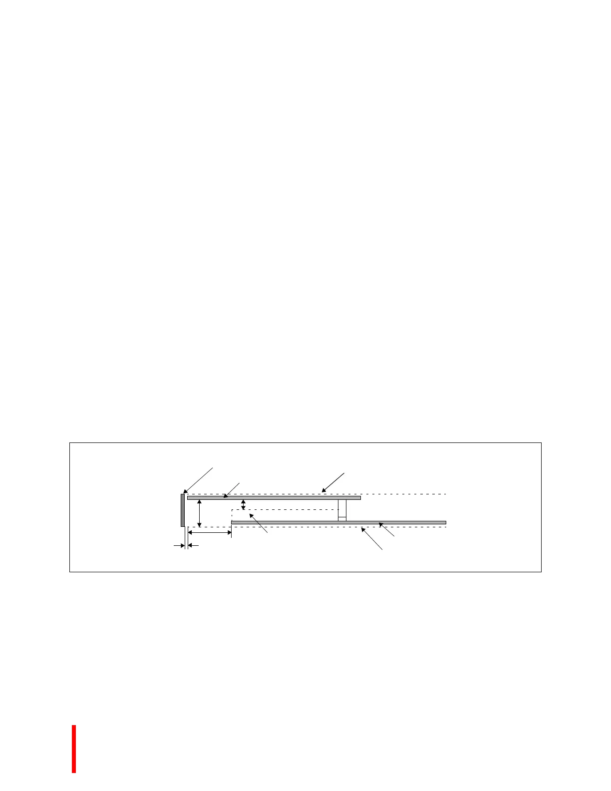
Figure 5-1. Squall II Module Component Height Allowance
0.626”
0.235”
0.040”
0.700”
PCI Panel (0.034”)
Squall II Module
Interboard Separation Plane
Cyclone EP
Interboard Separation Plane
Cyclone EP
Component Space