EasyManuals Logo

Intel i960 Series User Manual

Intel i960 Series
102 pages
To Next Page IconTo Next Page
To Previous Page IconTo Previous Page
Page #80 background imageLoading...
Page #80 background image
SQUALL II MODULE INTERFACE A
5-2
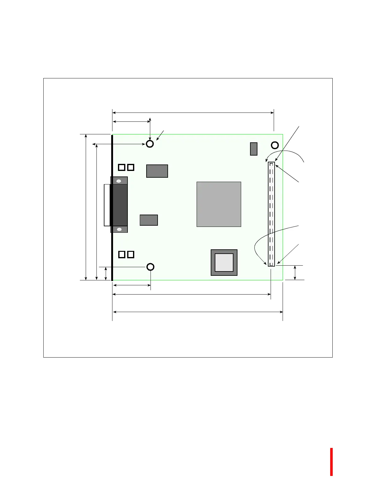
Figure 5-2. Squall II Module Dimensions
A
CYCLONE MICROSYSTEMS
COPYRIGHT 1995
Rev. xxxx
123-1234-12
Z2
U5
U4
U2
U3
U1
J1
Z1
all three holes are 0.120” DIA. thru
0.850”
0.850”
3.850”
3.650”
Pin 1
Pin 100
Pin 51
Pin 50
3.300
3.100”
0.200”
0.325”
NOTE:
Dimensions of J1 placement are to center line of the component in x axis and center line of pins 1 and 51
in y axis. For pin assignments, refer to Table 5-6, Squall II Module Pin Assignments (pg. 5-17).
3.535”
100-Pin Connector
Samtec TFM-150-32-SDLC

Table of Contents

Questions and Answers:

Question and Answer IconNeed help?

Do you have a question about the Intel i960 Series and is the answer not in the manual?

Intel i960 Series Specifications

General IconGeneral
BrandIntel
Modeli960 Series
CategoryComputer Hardware
LanguageEnglish

Related product manuals