A SQUALL II MODULE INTERFACE
5-13
The optional use of the EXTEND signal has been added to the interface to facilitate interfacing slower,
older DMA controller designs. EXTEND
may only be used in single transfer read cycles to extend the
time valid data is on the data bus. During an access with EXTEND
asserted, the DRAM controller
presents valid data on the bus with READY
asserted. The valid data remains on the bus and READY
remains asserted until the DRAM controller samples EXTEND negated at a rising edge of the PMCLK.
The controller then terminates the read cycle.
Assert BLAST
throughout the cycle. Using EXTEND during a burst access is not allowed and will
cause the DRAM controller to function improperly.
EXTEND
should be used during write cycles. Squall II Module logic can be used to delay the assertion
of ADS
until valid data is on the bus, making the use of EXTEND unnecessary. The DRAM controller
will not function correctly if EXTEND
is asserted during write cycles.
Figure 5-7, Squall II Master Read and Write Timing Diagram shows one wait state accesses.
The number of wait states depends on the clock frequency and memory speed. Refresh cycles may
delay READY
up to 10 additional clock cycles. Squall II Modules should be designed to handle fewer
wait states. Future base boards may incorporate faster memory systems.
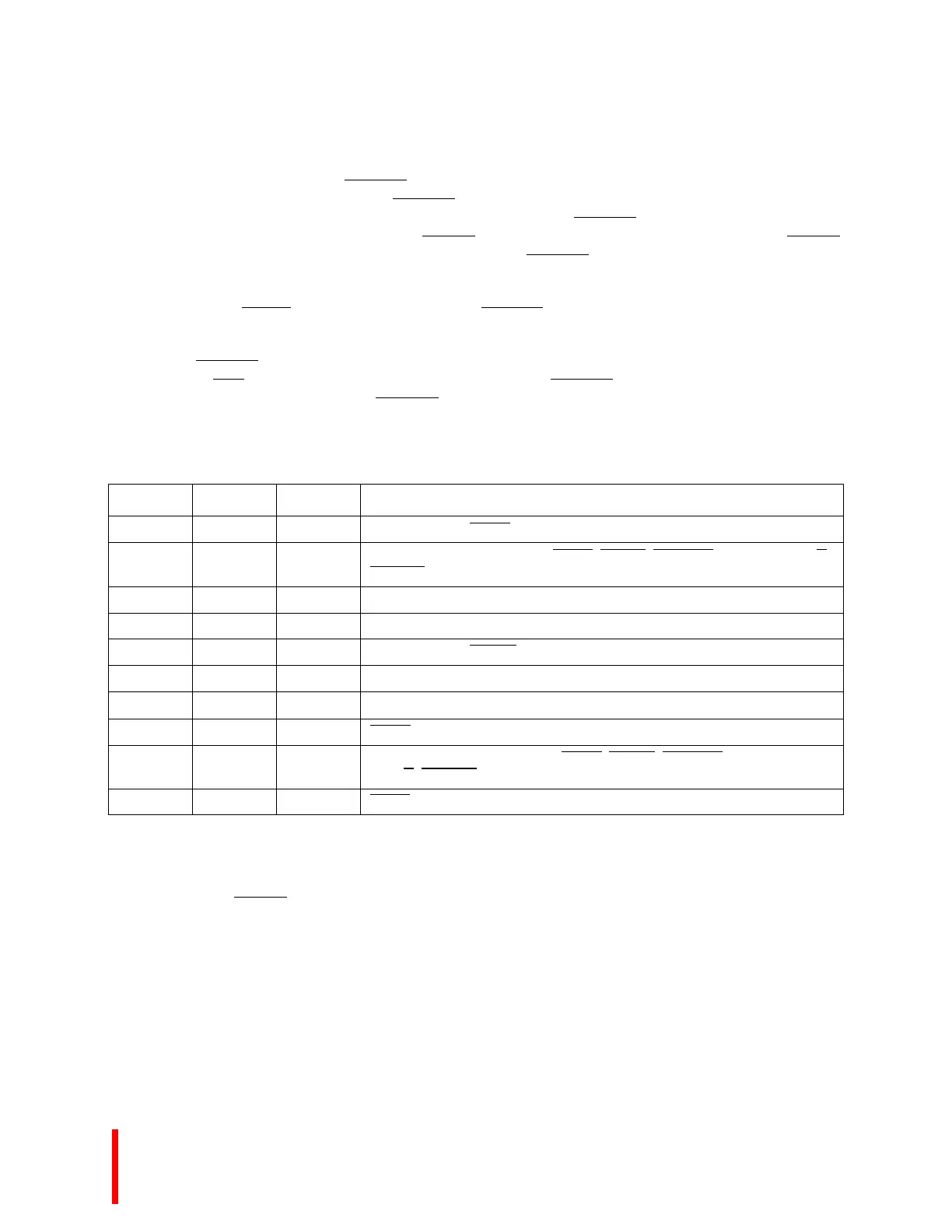
Table 5-5. Squall II Module Master Timing
Name Minimum Maximum Comment
t1 3 10 Clock to Output SQBG
t2 10 -- Setup to clock rising edge for SQBR, S_ADS, S_BLAST, S_A31:2, S_W/R,
S_BE3:0
t3 0 20 Clock to output D31:0, Read Cycle
t4 5 -- D31:0 hold from clock, Read Cycle
t5 3 10 Clock to Output READY
t7 10 -- Write Data Setup to Clock
t8 0 -- Write Data Hold from Clock
t9 0 30 SQBG Inactive to control signals three-stated
t10 0 -- Hold from clock rising edge for SQBR, S_ADS, S_BLAST, S_A31:2,
S_W/R
, S_BE3:0
t11 0 -- SQBR asserted to control outputs driven