Intel® Server Board S1200V3RP TPS On-board Connector/Header Overview
Revision 1.2
8.6 Fan Headers
The server board provides five SSI-compliant 4-pin fans (J7K1, J3K4, J8K1, J8K2 and J8B1) to
use as CPU and I/O cooling fans. 3-pin fans are supported on all fan headers. The pin
configuration for each of the 4-pin fan headers is identical and defined in the following tables.
One 4-pin fan header is designated as processor cooling fan:
- CPU fan (J7K1)
Three 4-pin fan headers are designated as system fans:
- System fan 1 (J3K4)
- System fan 2 (J8K1)
- System fan 3 (J8K2)
One 4-pin fan header is designated as a rear system fan:
- System fan 4 (J8B1)
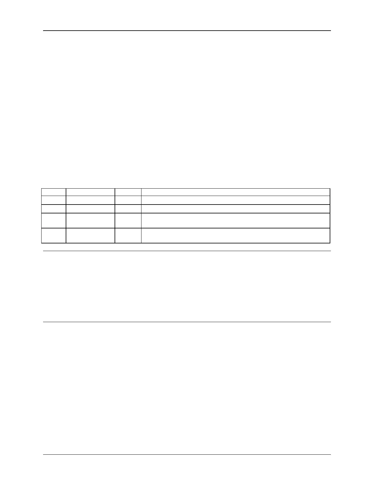
Table 53. SSI 4-pin Fan Header Pin-out (J7K1, J3K4, J8K1, J8K2, J8B1)
Ground is the power supply ground
FAN_TACH signal is connected to the BMC to monitor the fan speed
FAN_PWM signal to control fan speed
FAN_PWM signal to control fan speed FAN_TACH signal is connected to
the BMC to monitor the fan speed
Note: Intel Corporation server boards support peripheral components and can contain a number
of high-density VLSI and power delivery components that need adequate airflow to cool. Intel’s
own chassis are designed and tested to meet the intended thermal requirements of these
components when the fully integrated system is used together. It is the responsibility of the
system integrator that chooses not to use Intel developed server building blocks to consult
vendor datasheets and operating parameters to determine the amount of airflow required for
their specific application and environmental conditions. Intel Corporation cannot be held
responsible if components fail or the server board does not operate correctly when used outside
any of its published operating or non-operating limits.

 Loading...


