Intel® Server Board S1200V3RP TPS Intel® Light Guided Diagnostics
Revision 1.2
240VA fault
Fatal Error in processor initialization:
Processor family not identical
Processor model not identical
Processor core/thread counts not identical
Processor cache size not identical
Unable to synchronize processor frequency
Unable to synchronize QPI link frequency
11.3 BMC Boot/Reset Status LED Indicators
During the BMC boot or BMC reset process, the System Status LED and System ID LED are
used to indicate BMC boot process transitions and states. A BMC boot will occur when AC
power is first applied to the system. A BMC reset will occur after: a BMC FW update, upon
receiving a BMC cold reset command, and upon a BMC watchdog initiated reset. The following
table defines the LED states during the BMC Boot/Reset process.
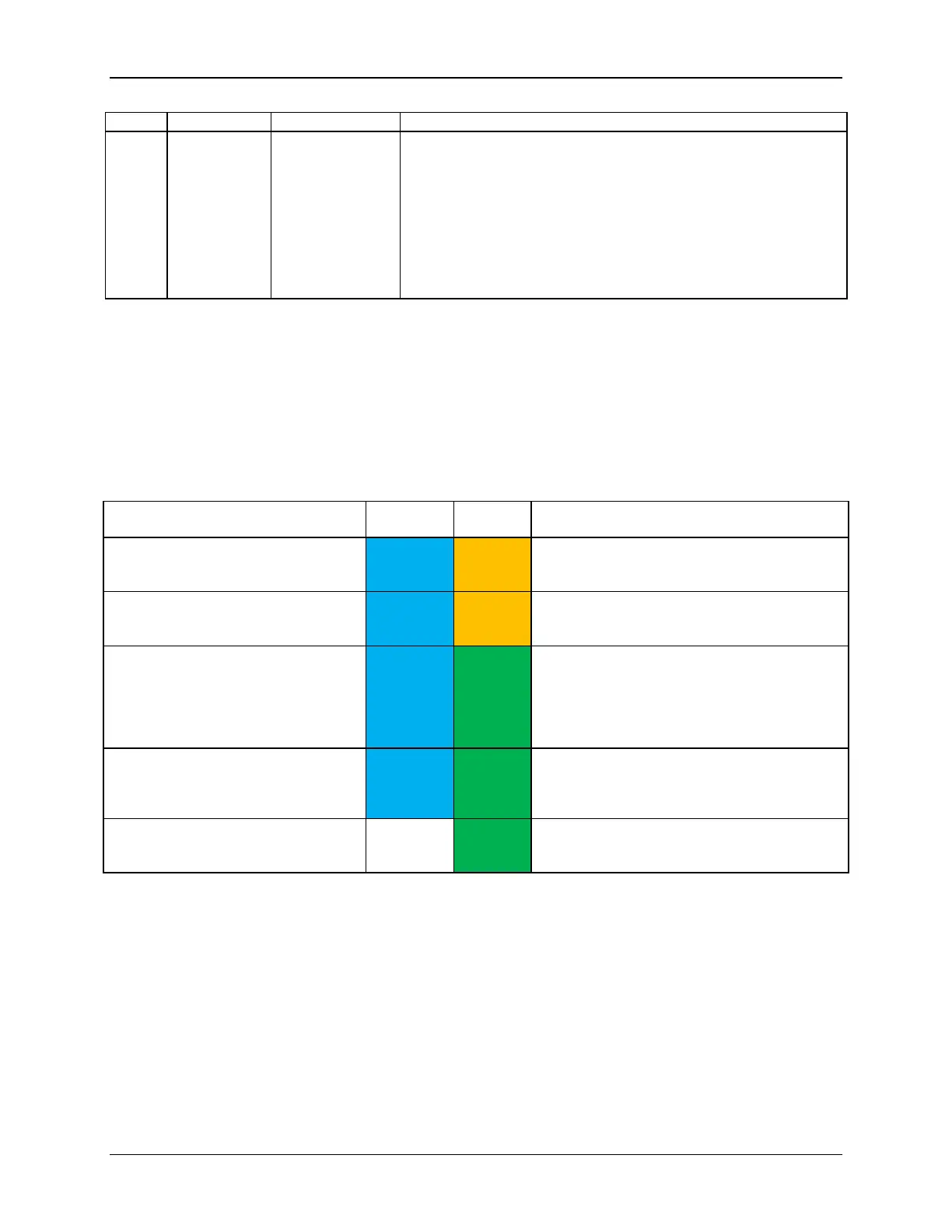
Table 60. BMC Boot/Reset Status LED Indicators
BMC/Video memory test failed
Nonrecoverable condition. Contact your Intel
®
representative for information on replacing this
motherboard.
Both Universal Bootloader (u-Boot)
images bad
Nonrecoverable condition. Contact your Intel
®
representative for information on replacing this
motherboard.
Blinking green indicates degraded state (no
manageability), blinking blue indicates u-Boot is
running but has not transferred control to BMC
Linux*. Server will be in this state 6-8 seconds
after BMC reset while it pulls the Linux* image
into flash.
Solid green with solid blue after an AC
cycle/BMC reset, indicates that the control has
been passed from u-Boot to BMC Linux* itself. It
will be in this state for ~10-~20 seconds.
End of BMC boot/reset process.
Normal system operation
Indicates BMC Linux* has booted and
manageability functionality is up and running.
Fault/Status LEDs operate as per usual.
11.4 Post Code Diagnostic LEDs
A bank of eight POST code diagnostic LEDs are located on the back edge of the server next to
the stacked USB connectors. During the system boot process, the BIOS executes a number of
platform configuration processes, each of which is assigned a specific hex POST code number.
As each configuration routine is started, the BIOS displays the given POST code to the POST
code diagnostic LEDs. The purpose of these LEDs is to assist in troubleshooting a system hang
condition during the POST process. The diagnostic LEDs can be used to identify the last POST
process to be executed. See Appendix D for a complete description of how these LEDs are read,
and for a list of all supported POST codes.

 Loading...


