EasyManuals Logo
Home>Intel>Server Board>S1200V3RP

Intel S1200V3RP Technical Product Specification

Intel S1200V3RP
270 pages
To Next Page IconTo Next Page
To Previous Page IconTo Previous Page
Page #97 background imageLoading...
Page #97 background image
Intel® Server Board S1200V3RP TPS On-board Connector/Header Overview
Revision 1.2
83
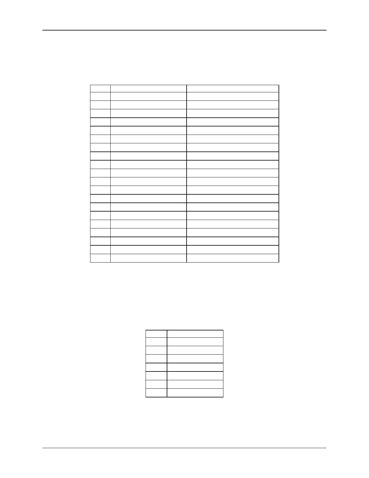
8.5.2 Display Port Connector
The following table details the pin-out definition of the Display Port connector (J8A1).
Table 43. Display Port Connector Pin-out (J8A1)
Pin
Signal Name
Description
1
OUT
ML_LANE 0 (P)
2
GND
Ground
3
OUT
ML_LANE 0 (N)
4
OUT
ML_LANE 1 (P)
5
GND
Ground
6
OUT
ML_LANE 1 (N)
7
OUT
ML_LANE 2 (P)
8
GND
Ground
9
OUT
ML_LANE 2 (N)
10
OUT
ML_LANE 3 (P)
11
GND
Ground
12
OUT
ML_LANE 3 (N)
13
GND
Ground
14
GND
Ground
15
I/O
AUX_CH (P)
16
GND
Ground
17
I/O
AUX_CH (N)
18
IN
HOT PLUG DETECT
19
PWR RTN
RETURN DP_PWR
20
PWR OUT
DP_PWR
8.5.3 SATA Connectors
The server board provides up to 6 SATA connectors: SATA-0 (J1K4), SATA-1 (J1K1), SATA-2
(J1K5), SATA-3 (J1K2), SATA-4 (J2K5), and SATA-5 (J2K3).
The pin configuration for each connector is identical and defined in the following table:
Table 44. SATA Connector Pin-out (J1K4, J1K1, J1K5, J1K2, J2K5, J2K3)
Pin
Signal Name
1
GND
2
TXP
3
TXN
4
GND
5
RXN
6
RXP
7
GND
8.5.4 Serial Port Connectors
The server board provides one external DB9 Serial A port (J9A1) and one internal 9-pin Serial B
header (J9A2). The following tables define the pin-outs.

Table of Contents

Other manuals for Intel S1200V3RP

Questions and Answers:

Question and Answer IconNeed help?

Do you have a question about the Intel S1200V3RP and is the answer not in the manual?

Intel S1200V3RP Specifications

General IconGeneral
BrandIntel
ModelS1200V3RP
CategoryServer Board
LanguageEnglish

Related product manuals