EasyManuals Logo
Home>Intel>Server Board>S1200V3RP

Intel S1200V3RP Technical Product Specification

Intel S1200V3RP
270 pages
To Next Page IconTo Next Page
To Previous Page IconTo Previous Page
Page #91 background imageLoading...
Page #91 background image
Intel® Server Board S1200V3RP TPS On-board Connector/Header Overview
Revision 1.2
77
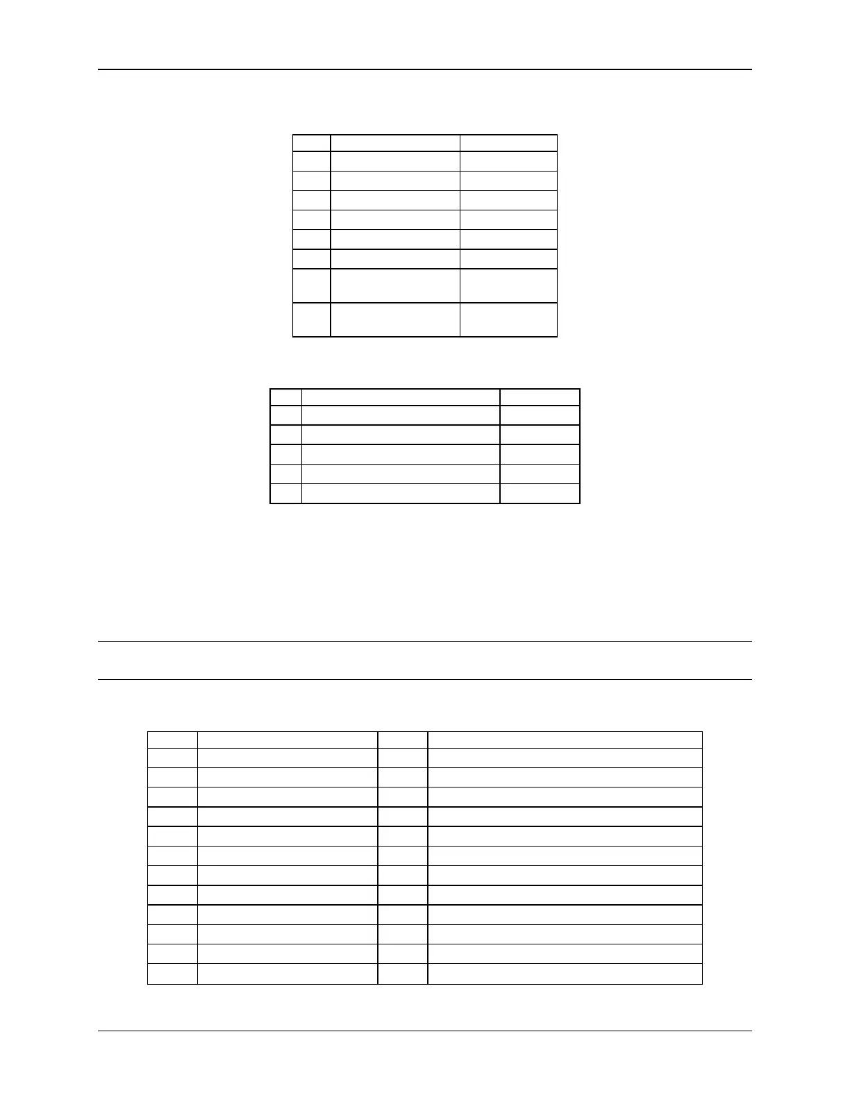
Table 27. CPU Power Connector Pin-out (J9B1)
Pin
Signal
Color
1
GND of Pin 5
Black
2
GND of Pin 6
Black
3
GND of Pin 7
Black
4
GND of Pin 8
Black
5
+12 Vdc CPU1
Yellow/black
6
+12 Vdc CPU1
Yellow/black
7
+12 Vdc
DDR3_CPU1
Yellow/black
8
+12 Vdc
DDR3_CPU1
Yellow/black
Table 28. Power Supply Auxiliary Signal Connector Pin-out (J9C3)
Pin
Signal
Color
1
SMB_CLK_FP_PWR_R
Orange
2
SMB_DAT_FP_PWR_R
Black
3
SMB_ALRT_3_ESB_R
Red
4
3.3 V SENSE-
Yellow
5
3.3 V SENSE+
Green
8.3 System Management Headers
8.3.1 Intel
®
Remote Management Module 4 Dedicated NIC Connector
A 30-pin Intel
®
RMM4 connector (J4C1) and a 7-pin Intel
®
RMM4 Lite connector (J4B1) are
included on the server board to support the optional Intel
®
Remote Management Module 4
dedicated NIC module. This server board does not support third-party management cards.
Note: This connector is not compatible with the previous generation Intel
®
Remote Management
Modules (Intel
®
RMM/RMM2/RMM3)
Table 29. Intel
®
RMM4 Dedicated NIC Module Connector Pin-out (J4C1)
Pin
Signal Name
Pin
Signal Name
1
3V3_AUX
2
MDIO
3
3V3_AUX
4
MDC
5
GND
6
TXD_0
7
GND
8
TXD_1
9
GND
10
TXD_2
11
GND
12
TXD_3
13
GND
14
TX_CTL
15
GND
16
RX_CTL
17
GND
18
RXD_0
19
GND
20
RXD_1
21
GND
22
RXD_2
23
GND
24
RXD_3

Table of Contents

Other manuals for Intel S1200V3RP

Questions and Answers:

Question and Answer IconNeed help?

Do you have a question about the Intel S1200V3RP and is the answer not in the manual?

Intel S1200V3RP Specifications

General IconGeneral
BrandIntel
ModelS1200V3RP
CategoryServer Board
LanguageEnglish

Related product manuals