23
(1) Mark the hole location. The location of the holes is shown in the dimension drawings in
the appendix.
(2) Fix the screws or bolts to the marked locations..
(3) Position the drive onto the wall.
(4) Tighten the screws in the wall securely.
Note:
1. The flange installation braket is needed in the flange installation of 1.5~30kW
inverters, which the flange installation of 37~200kW inverters does not need the
installation braket.
2. 220~315kW inverters need optional base in the floor installation.
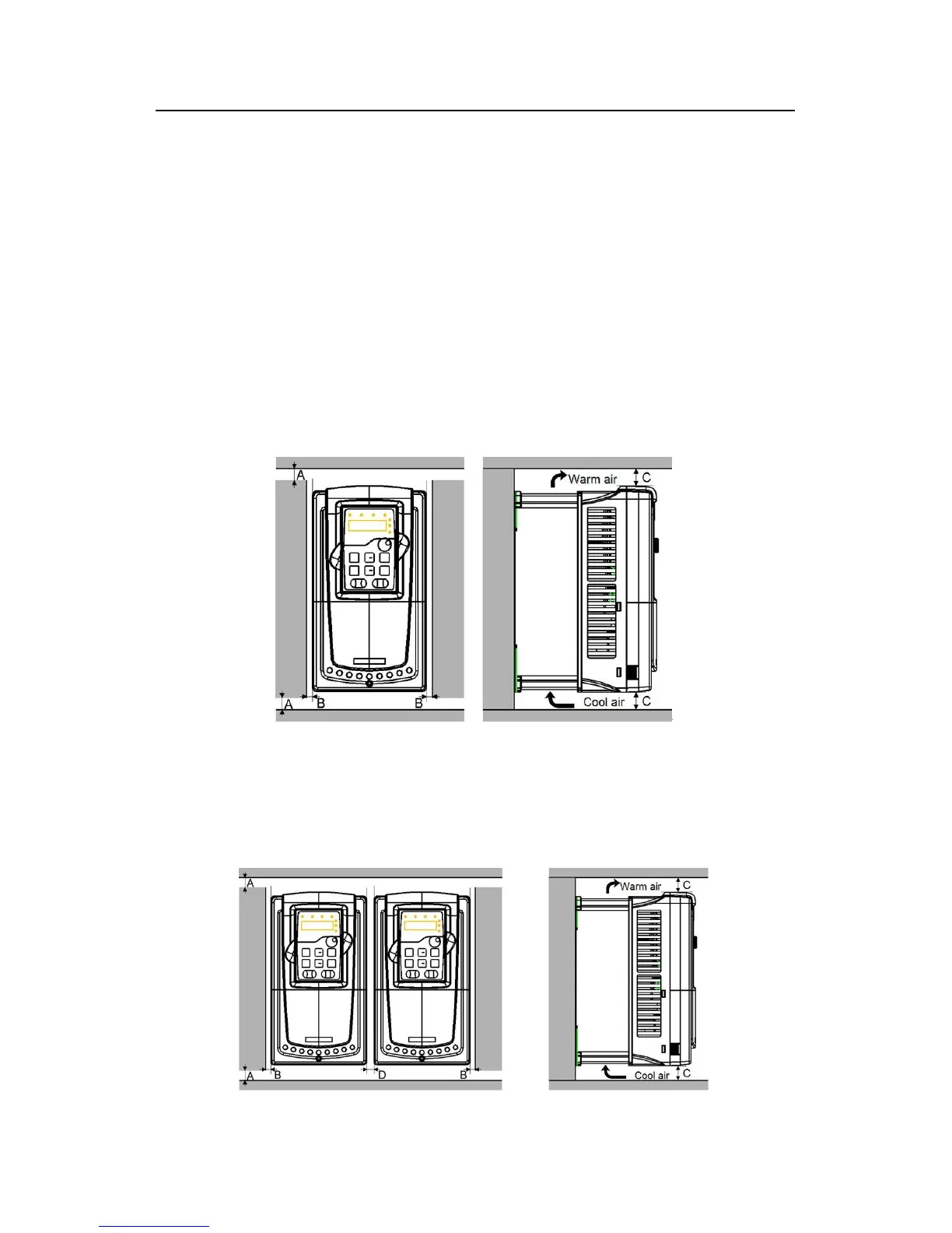
4.2.4 Single installation
Fig 4-3 Single installation
Note:The minimum space of B and C is 100mm.
4.2.5 Multiple installations
Parallel installation