Goodrive300-21 integrated machine for air compressor Installation guidance
-6-
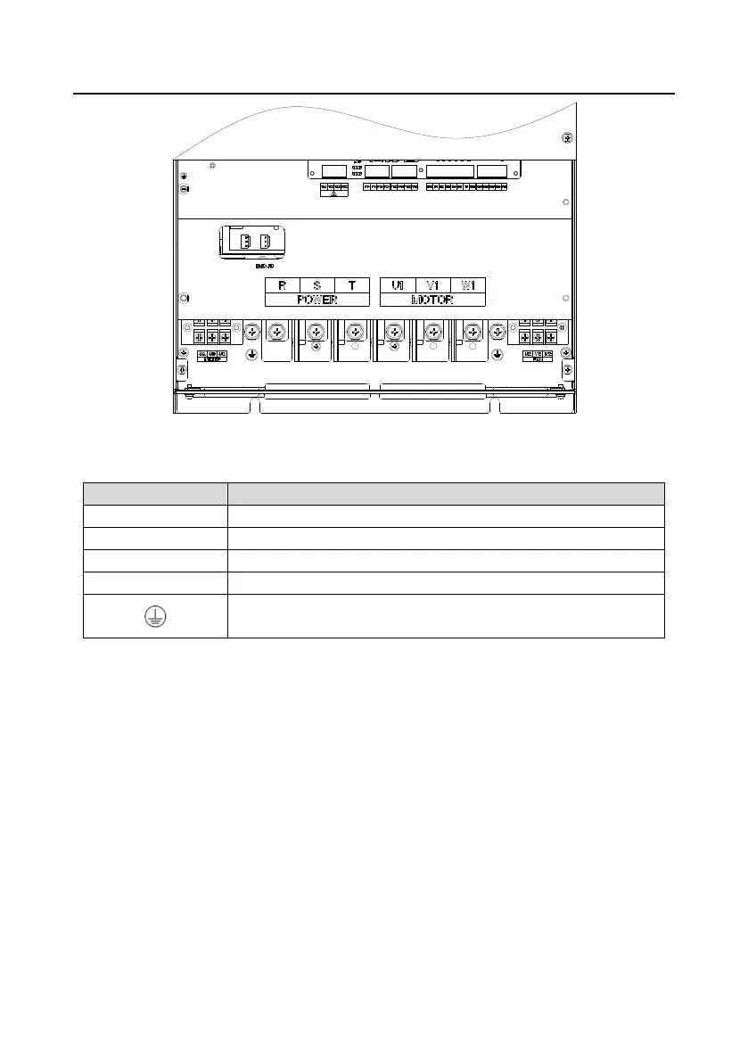
Figure 2-3 AC380V 45–90kW
Table 2-1 Terminal instruction
Used for input connection of optional contactor components.
3PH AC input terminals, connecting to the grid
3PH AC output terminal, connected to main motor of air compressor
3PH AC output terminal, connected to the fan
Grounding terminal of safety protection, each machine must be
grounded.
Note:
1. Do not use asymmetrical motor cables. Do not use asymmetrically constructed motor cable. If
there is a symmetrically constructed ground conductor in the motor cable in addition to the
conductive shielding layer, ground the ground conductor at the inverter end and motor end.
2. Route the motor cable, input power cable and control cable separately.
3. Before powering on the system, ensure that U1/V1/W1 or U2/V2/W2 are not short-circuited to PE
on the output side. Otherwise, tripping may occur on the power distribution cabinet when the
system is being powered on.

 Loading...


