Goodrive300-21 integrated machine for air compressor Optional parts
-92-
Note: If users need to install a contactor component, it is recommended to install the components
onto the pedestal first, then, install the pedestal onto the integrated machine.
B.4.3 Installation diagram of optional pedestal
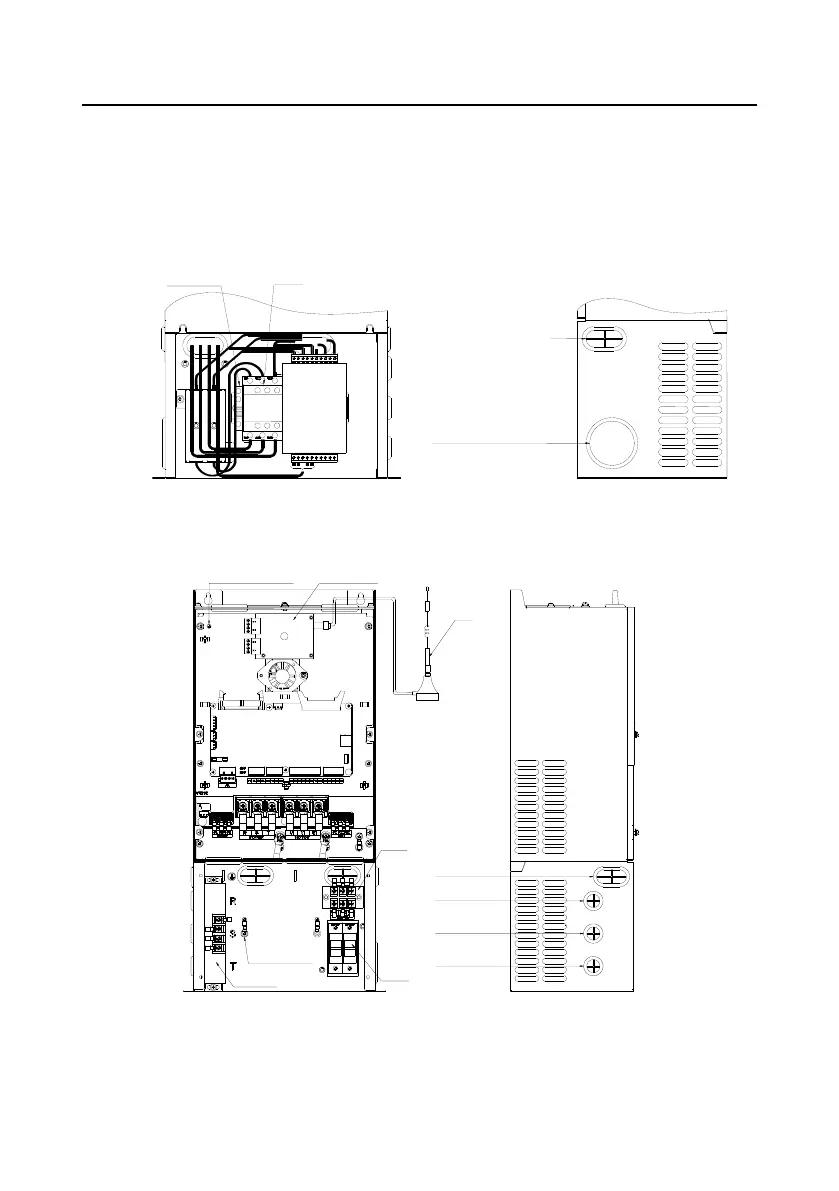
Please refer to the following diagram if it is needed to install optional contactor component on the
installation pedestal.
Through-hole of U2, V2 and W2 cable of fan
Through-hole of U1, V1 and W1 cable of main
motor
Through-hole of U3, V3 and W3
cable of master cooling fan
Rear view of pedestal Rightside view of pedestal
Contactor
Terminal fixed part for guide rail
Back-up
Figure B-12 Wiring diagram of the back of optional pedestal
Remote data collection
terminal
Fuse
Connection
terminal
Current transformer
Secondary side of
current transformer
Grounding terminal
Through-hole of AC power
ground cable
R phase through-hole of
AC power
S phase through-hole of
AC power
T phase through-hole of
AC power
Grounding of the shielded cable of
remote data collection terminal
Front view of the
integrated machine
Leftside view of the
integrated machine
Antenna
Figure B-13 Installation diagram of optional pedestal

 Loading...


