Goodrive300-21 integrated machine for air compressor Installation guidance
-7-
2.2 Wiring and terminal instruction of control circuit
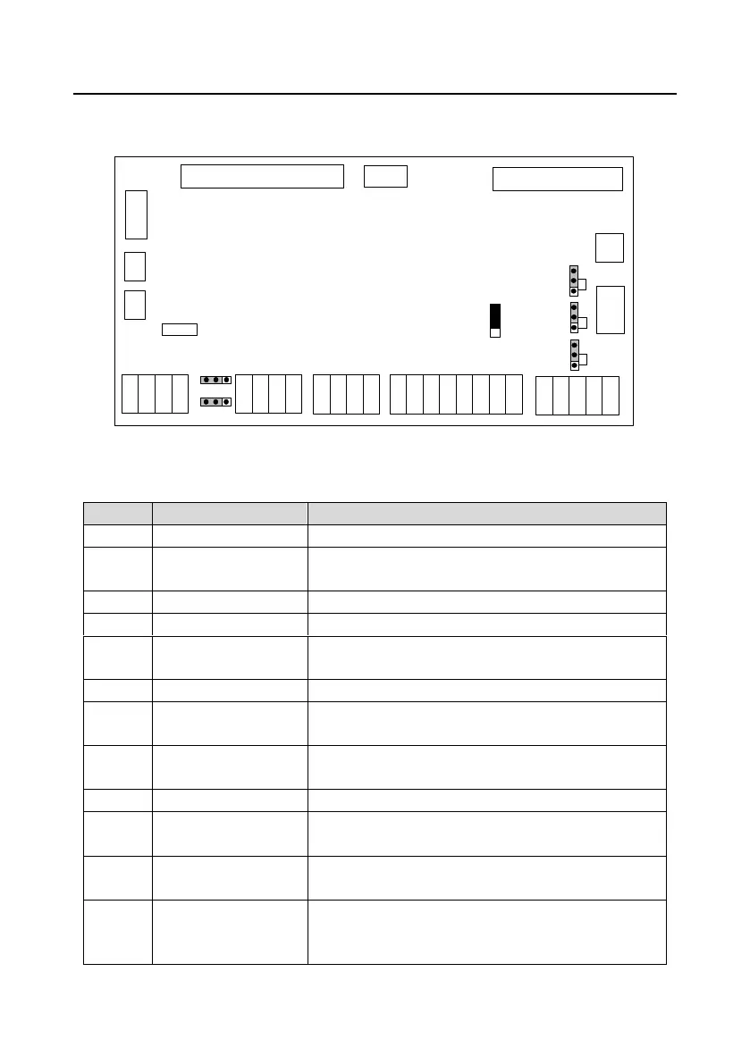
2.2.1 Control circuit layout diagram
TA1
TC1
TA2
TC2
P1+
P1-
P2+
P2-
PTA1
PTB1
PTA2
PTB2
S1
S2
S3
S4
S5
Y1
COM
+24V
GND
485+
485-
Goodrive300-21 control board
34PIN
26PIN
3 1
CN9
CN1 CN2
CN17
CN7
CN8
CN10
CN11 CN12 CN13
CN14
CN15
F1
CN6
J7
J8
COM
+24V
GND
485+
485-
+24V
GND
SW1
+24V
COM
J5
485
ON
PE
CGND
PE
CN14-5
GND
ON
J9
J6
VI
I V
PE/CGND
Figure 2-4 Control circuit layout diagram
Table 2-2 Terminal instruction
Connected to drive board, master control signal wire
Outputs +24V power, can be used to power up external
GPRS.
Connected to drive board, fan control signal wire
Reserved interface, connected with keypad
Connected to touch screen, provide +24V power and 485
communication interface
Multi-function input terminal
Temperature detection
terminal
Connected to PT100 temperature sensor
Pressure detection
terminal
Connected to pressure sensor
Connected to solenoid valve or contactor coil
Protection against short circuit of solenoid valve/contactor
coil terminal or overcurrent
220V/110V voltage input
terminal
Connected to internal power frequency transformer
220V voltage selection
terminal
Select this terminal with jumpers when users select the
solenoid valve with 220V coil or the contactor.
Note: The default selection is 220V voltage terminal.

 Loading...


