Goodrive300-21 integrated machine for air compressor Commissioning guidelines
-12-
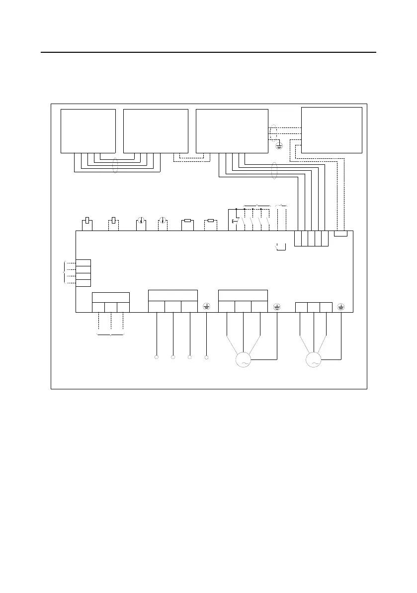
4 Commissioning guidelines
4.1 Wiring diagram of integrated machine system
M
TA1
TC1
P1+
P1-
P2+
P2-
PTA1
PTB1
PTA2
PTB2
S1
S2
S3
S4
S5
Y1
COM
Pressure sensor
interface
PT100 temp. sensor
interface
Multi-function
terminal
Output voltage
220/110VAC
COM
24V 4-20mA
E-stop
signal
Internal fault
signal output
Customized
R
S
T
U1
V1
W1
UA UB
UC
+24V
GND
485+
485-
PE\CGND
PE
485A-
485A+
GND
+24V
485C+
485C-
input
485B+
485B-
PE
PE
485A-
485A+
GND
+24V
485C-
485C+
PE
485-
485+
GND
+24V
GD300-21
GD300-21
HMI
HMI
Solenoid valve
coil
Contactor coil
(optional)
TA2
TC2
Exhaust
pressure
Auxillary
pressure
Oil gas temp.
Auxillary temp.
GND
+24V
3
1
CN17
PT100
PT100
AC input power
3
Motor shell grounding
R
S
T PE
Main motor
M
3
Motor shell grounding
Fan
POWER
MOTOR
METER
U2 V2 W2
RS485 joint control
RS485
Interface for optional parts
+24V
GND
485-
485+
Remote data collection
terminal (optional)
+5V
GND
485A-
485A+
J1 J2
CN15
+24V
GND
485+
485-
Interfaces for
optional
parts
Figure 4-1 Wiring diagram of integrated machine system
Note: The solid line represents the recommended wiring diagram which carries the least wiring for
ensuring system operation. The dotted line represents the wiring diagram used when discrepancy
occurred to the configuration of integrated machine.
4.2 Recommended wiring process
The terminal layout of 15–22kW, 30kW–37kW and 45–90kW slightly differs from each other. 15–
22kW and 45–90kW are taken as examples for wall-mounting wiring.

 Loading...


