Goodrive300-21 integrated machine for air compressor Optional parts
-82-
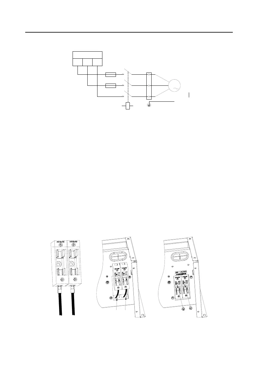
Cooling fan of the
main motor
to the control board of
integrated machine
3
M
TA2,TC2
UA
METER
UB
UC
METER connection
terminal of integrated
machine
conversion terminal
U3, V3, W3
Figure B-1 Electrical diagram of contactor component
B.1.3 Fuse pedestal installation
The fuse pedestal must be installed according to the following procedures, otherwise any wiring
attempt would fail.
Step 1: Connect the cable to the bottom of the two pedestals respectively. The yellow cable (cable
mark is FU-2) should connected to the left side while the green cable (cable mark is FU-4)
should be connected to the right side.
Step 2: Yellow cable goes through the through-hole on the left side and green cable goes through the
through-hole on the right side.
Step 3: Put the fuse pedestal into the installation stand and fix the fuse pedestal with M4 pan head
screw.
Step 4: Mount the fuse into the fuse pedestal.
Step 5: Fuse pedestal installation is completed.
Yellow cable Green cable
1
2 3
(FU-2)
(FU-4)

 Loading...


