Goodrive300-21 integrated machine for air compressor Installation guidance
-9-
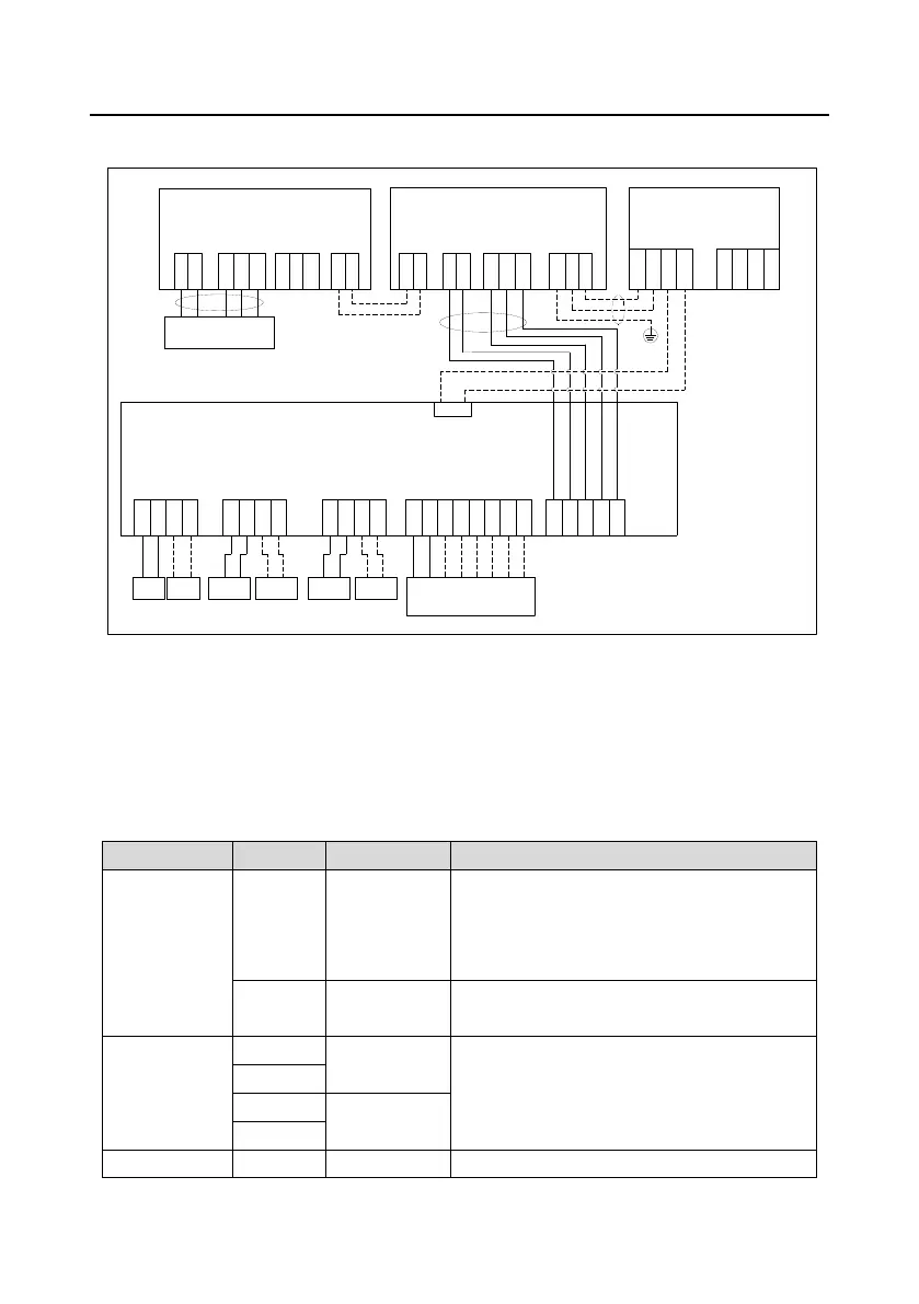
2.2.2 Wiring diagram of control circuit
TA1
TC1
TA2
TC2
P1+
P1-
P2+
P2-
PTA1
PTB1
PTA2
PTB2
S1
S2
S3
S4
S5
Y1
COM
Solenoid
valve
+24V
GND
485+
485-
PE\CGND
GD300-21 control board
+24V
GND
485A+
485A-
PE
485C+
485C-
HMIHMI
+24V
GND
485A+
485A-
PE
485C+
485C-
485B-
485B+
PE
RS485 joint control
Y1: Fault output signal
Oil gas temp.
Pressure sensor
interface
24V 4-20mA
PT100 temperature
sensor interface
Multi-function terminal
Output voltage
220/110VAC
coil
Contactor
coil
Exhaust
pressure
Auxiliary
pressure
S1:E-stop signal (NC)
S2-S5: Customized input
Auxiliary
temp.
+24V
GND
13
CN17
COM
485B-
485B+
PE
GD300-21
control board
RS485
J1
485+
485-
+24V
GND
485A-
GND
+5V
485A+
J2
(Optional)
Remote data collection terminal
Figure 2-7 Wiring diagram of control circuit
Note: The solid line represents the recommended wiring diagram which carries the least wiring for
ensuring system operation. The dotted line represents the wiring diagram used when discrepancy
occurred to the configuration of integrated machine.
2.2.3 User terminal instruction of control circuit
Table 2-1 User terminal instruction of control circuit
Used to externally provide +24V±5% power
supply, max. output current: 1A
Used for powering up GPRS, touch screen
module
Reference ground of the +24V power supply
Temperature
analog signal 1
1. Resolution rate: 1°C
2. Range: -20°C–150°C
3. Detection precision: 3°C
Temperature
analog signal 2
1. Input range: Current and voltage is optional,

 Loading...


