Goodrive300-21 integrated machine for air compressor Installation guidance
-8-
110V voltage selection
terminal
Select this terminal with jumpers when users select the
solenoid valve with 110V coil or the contactor.
Access terminal for 485
communication terminal
resistor
485 corresponds to access terminal resistor. Does not
connect terminal resistor by default.
Short-circuit terminal of
PE and GND
ON corresponds to short-circuit. No short circuit by default
Corresponds to P1+, P1- pressure analog signal selection. I
corresponds to current signal, V to voltage signal. The
default is current input signal.
Corresponds to P2+, P2- pressure analog signal selection. I
corresponds to current signal, V to voltage signal. The
default is current input signal.
PE/CGND selection
terminal
485 communication is non-isolation mode. CN14-5 is short
circuited with PE by default.
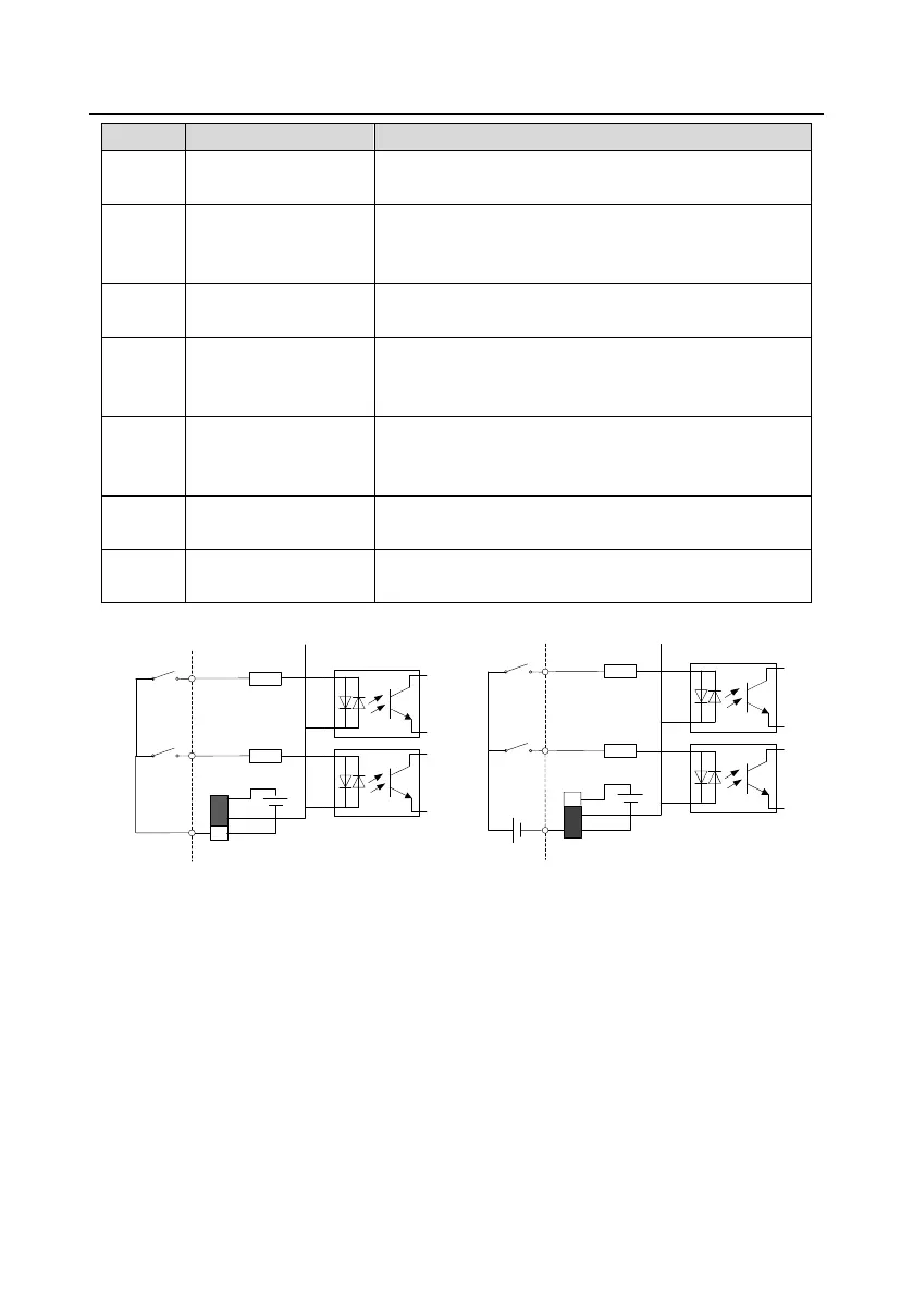
Set to +24V terminal by default. See details at Figure 2-5
and Figure 2-6.
●
●
●
COM
+24V
PW
COM
+24V
•
•
S1
S2
•
SW1
COM
+24V
PW
COM
+24V
•
•
S1
S2
•
●
●
●
+24V
SW1
Figure 2-5 Internal power (NPN mode)
Figure 2-6 External power (PNP mode)
When digital input adopts internal +24V, set the toggle switch according to Figure 2-5 and short circuit
+24V with PW. When digital input adopts external +24V, set the toggle switch according to Figure 2-6
and short circuit COM with PW.

 Loading...


