Goodrive300-21 integrated machine for air compressor Optional parts
-96-
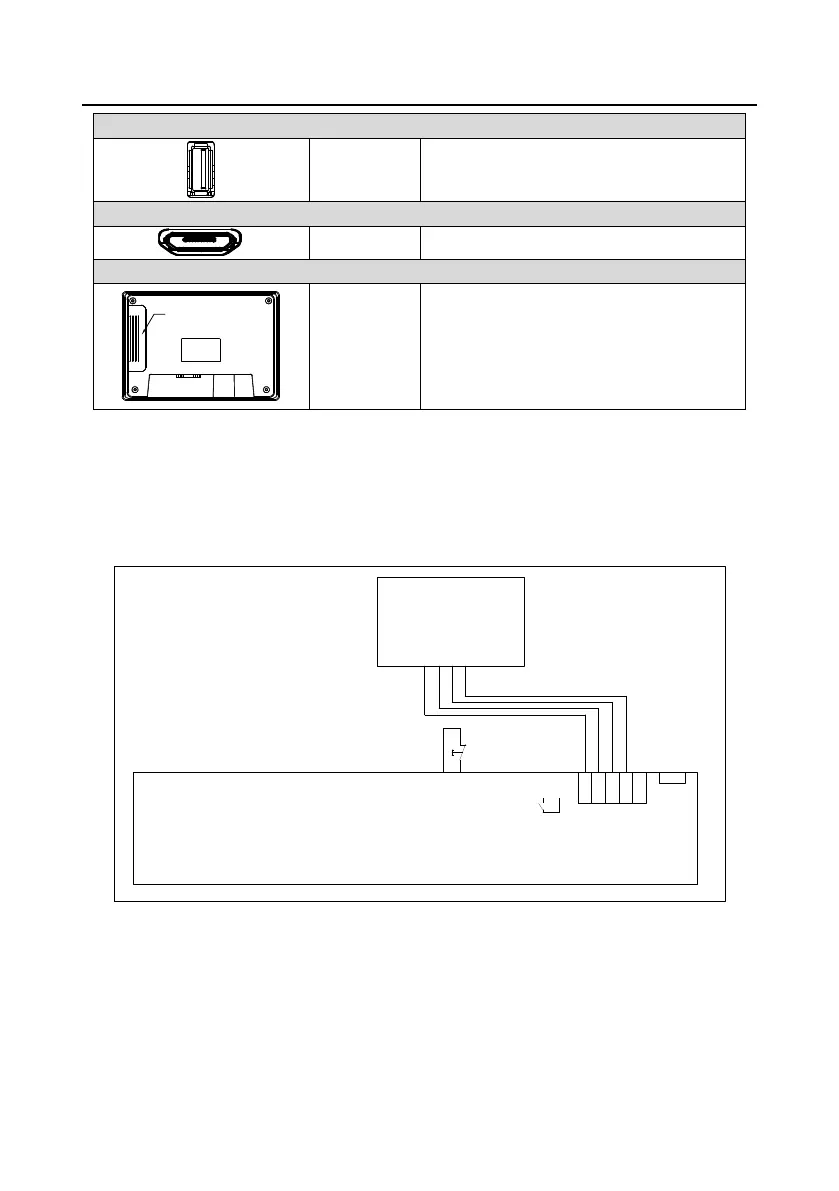
Used to connect external peripherals such as
the USB disk and barcode scanning device
Used for program download and debugging
Supported modules: FLink, FLink-2G, FLink-4G,
and FLink-WiFi
B.5.3 Wiring description
In order to drive and manage the air compressor better, use the provided RS485 communication
cable, of which one end is connected to the touch screen power supply port and DB9 serial port and
the other is connected to the inverter control board terminal (CN 7).
TA1
TC1
P1+
P1-
P2+
P2-
PTA1
PTB1
PTA2
PTB2
S1
S2
S3
S4
S5
Y1
COM
Pressure sensor
interface 24V
4-20mA
PT100 tempreture
sensor interface
Multi-function terminals
Input voltage
220/110VAC
COM
Emergency stop
signal wiring
+24V
GND
485+
485-
PE
PE
485A-
485A+
GND
+24V
485C+
485C-
485B+
485B-
PE
TA2
TC2
GND
+24V
3
1
CN17
HMI
GD300-21 control board
RS485 communication cable
Figure B-15 Standard touch screen wiring diagram
Note:
The touch screen is provided with a non-shielded RS485 communication cable. If a shielded
cable is required, please order separately.
For details about the touch screen use, please see Touch Screen HMI User Manual.

 Loading...


