Goodrive300-21 integrated machine for air compressor Optional parts
-97-
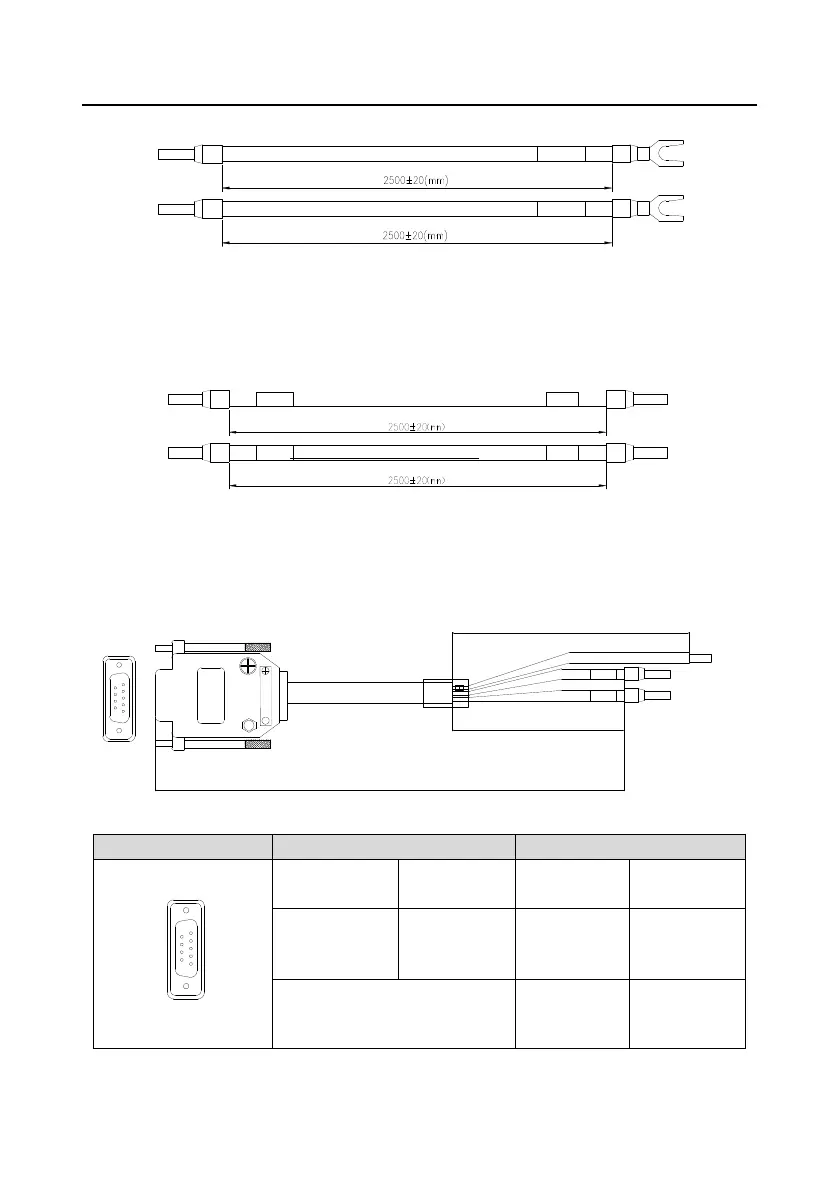
B.5.4 Cable description
E-stop signal
E-stop signal
Figure B-16 Emergency stop cable diagram
Note: The emergency stop cable is used for emergency stop control when a device fault occurs and it
is often connected to the S1 terminal and COM terminal.
Figure B-17 Touch screen power supply cable diagram
Note: As shown in Figure B-15, the touch screen power supply interface is connected to the CN17 of
inverter control board.
5
9
1
6
P1
5
9
1
6
Female
485A-
485A+
P3
P4
P2
2500±20(mm)
100±20(mm)
260±20(mm)
Figure B-18 Touch screen communication cable diagram
Shield layer
grounding cable

 Loading...


