Goodrive300-21 integrated machine for air compressor Function description
-62-
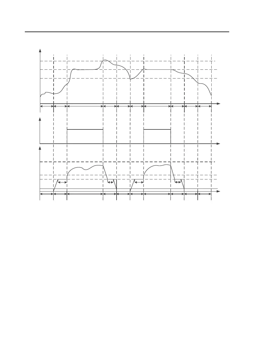
(2) The pressure and running frequency control of air compressor during running is shown as below:
A B C D E F C G H A
Time
Current
pressure
P18.05
P18.07
P18.06
0
A B C D E F C G H A
Time
Current
running
frequency
P00.04
P18.12
0
P18.11
P01.15
P18.15 P18.13 P18.15 P18.14
Load
valve
0
1
In above figure, P18.05 is unloading pressure, P18.06 is loading pressure and P18.07 is the set
pressure.
P00.04 is upper limit frequency, P18.11 is lower limit value of loading running frequency, P18.12 is
no-load frequency and P01.15 is stop speed. In the figure, the process instruction for A–H stages are
listed as below:
A: Stand-by state
B: Beginning stage of starting, the duration time is P18.15 (including part of ACC time P00.11)
C: Constant pressure exhaust stage of loading, pressure PID adjustment is valid
D: Unloading stage, the duration time includes part of DEC time P00.12 and P18.13
E: Sleep stage, the inverter does not run
F: Wake-up and starting stage, the duration time is P18.15 (including part of ACC time P00.11)
G: Beginning of stop, the duration time includes part of DEC time P00.12 and P18.14

 Loading...


