IPE300 series engineering VFD Basic operation guidelines
-44-
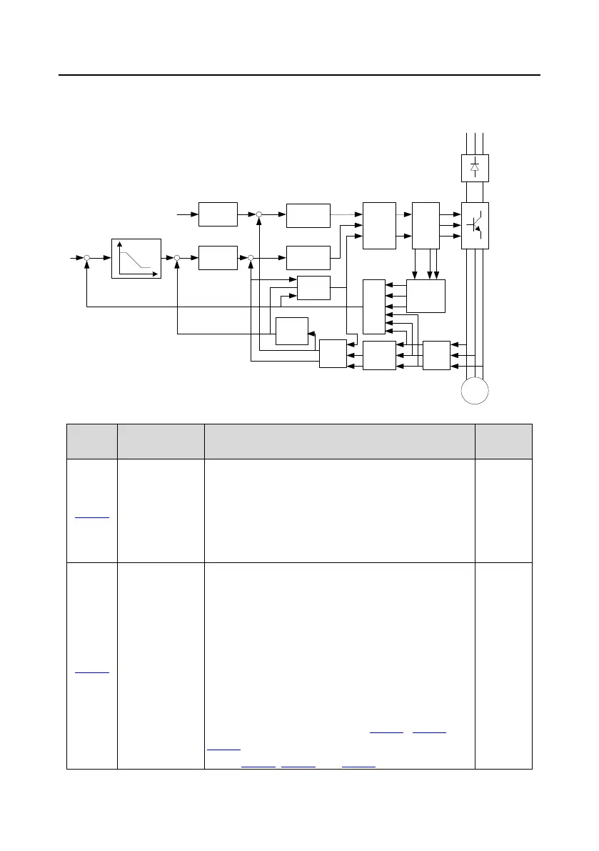
As the vector control algorithm is complicated, exercise caution before modifying vector control
function parameters.
Calculate i
m
ACR
exciting
current
Flux linkage
observation
Current
detection
Position
observation
Speed
identific
ation
Voltage
detection
ACR
torque current
Calculate i
T
Park
conversion
PWM
pulse
Rectifier
bridge
IGBT
bridge
Motor
Park
conversio
n
Clark
conversion
φ
+
-
+
-
+
-
U
V
U
W
Uu
i
U
i
V
i
W
U
V
U
W
Uu
i
M
i
T
1w
r
1w
r
φ
i
T
R S T
0: Sensorless vector control (SVC) mode 0
1: Sensorless vector control (SVC) mode 1
2: Space voltage vector control mode
3: Closed-loop vector control mode
Note: If 0, 1 or 3 is selected, it is required to carry out
motor parameter autotuning first.
Motor parameter
autotuning
0: No operation
1: Rotary autotuning.
Comprehensive motor parameter autotuning. It is
recommended to use rotating autotuning when high
control accuracy is needed.
2: Static autotuning 1 (comprehensive autotuning); static
autotuning 1 is used in cases where the motor cannot be
disconnected from load.
3: Static autotuning 2 (partial autotuning); when the
present motor is motor 1, only P02.06, P02.07, and
P02.08 are autotuned; when the present motor is motor
2, only P12.06, P12.07, and P12.08 are autotuned.

 Loading...


